The Ambulance – Completed October, 2017
First posting – August, 2015
The Starkville Civil War Arsenal has started construction on a Wheeling ambulance. When the ambulance is completed and added to the collection it will make The Starkville Civil War Arsenal the first and only collection in the country where visitors will be able to view all of the Civil War field artillery carriages and associated support vehicles in one place at the same time. Pictures of the ambulance under construction will be posted periodically as progress allows. I hope you enjoy the journey to the completion of this project.
The ambulance is not usually thought of when the topic of Civil War field artillery is discussed, but the ambulance had a definite presence in the artillery parks of the American Civil War as documented in the following General Orders:
[General Orders No. 85 Published on 24 August 1863] AMBULANCE CORPS. HEAD-QUARTERS, ARMY OF THE POTOMAC, August 24, 1863.
The following revised regulations for the organization of the Ambulance Corps, and the management of the Ambulance Trains, are published for the government of all concerned, and will be strictly observed: 1. The Army Corps is the unit of organization for the ambulance corps, and the latter will be organized upon the basis of the Captain as the commandant of the corps, one 1st Lieutenant for each division, one 2d Lieutenant for each brigade, one Sergeant for each regiment. 2. The Privates of this corps will consist of two men and one driver to each ambulance, and one driver to each medicine wagon. The two-horse ambulances only will be used, and the allowance, until further orders, to each corps, will be upon the basis of three to each regiment of infantry, two to each regiment of cavalry, one to each battery of artillery, to which it will be permanently attached, and two to the head-quarters of each army corps, and two army wagons to each division. Each ambulance will be provided with two stretchers…
For more information on the ambulance and the ambulance corps go to:
http://history.amedd.army.mil/booksdocs/civil/lettermanmemoirs/bennett_master.html
Confederate armies also followed these guidelines as closely as possible with the equipment they had available.
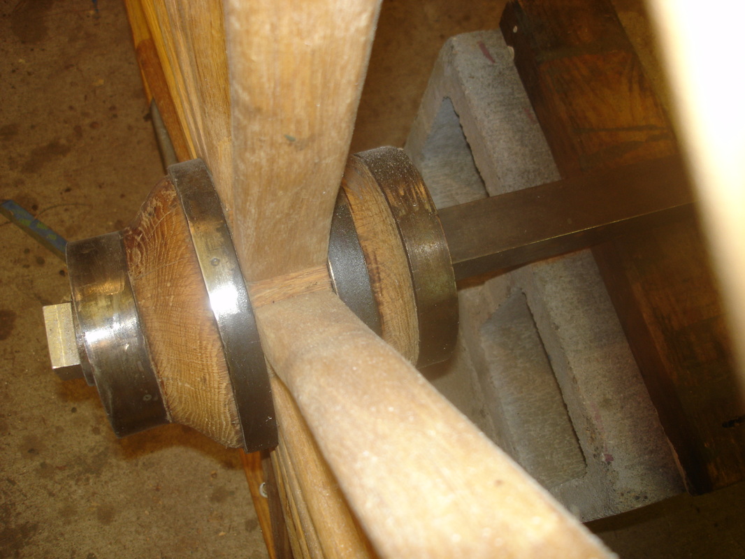
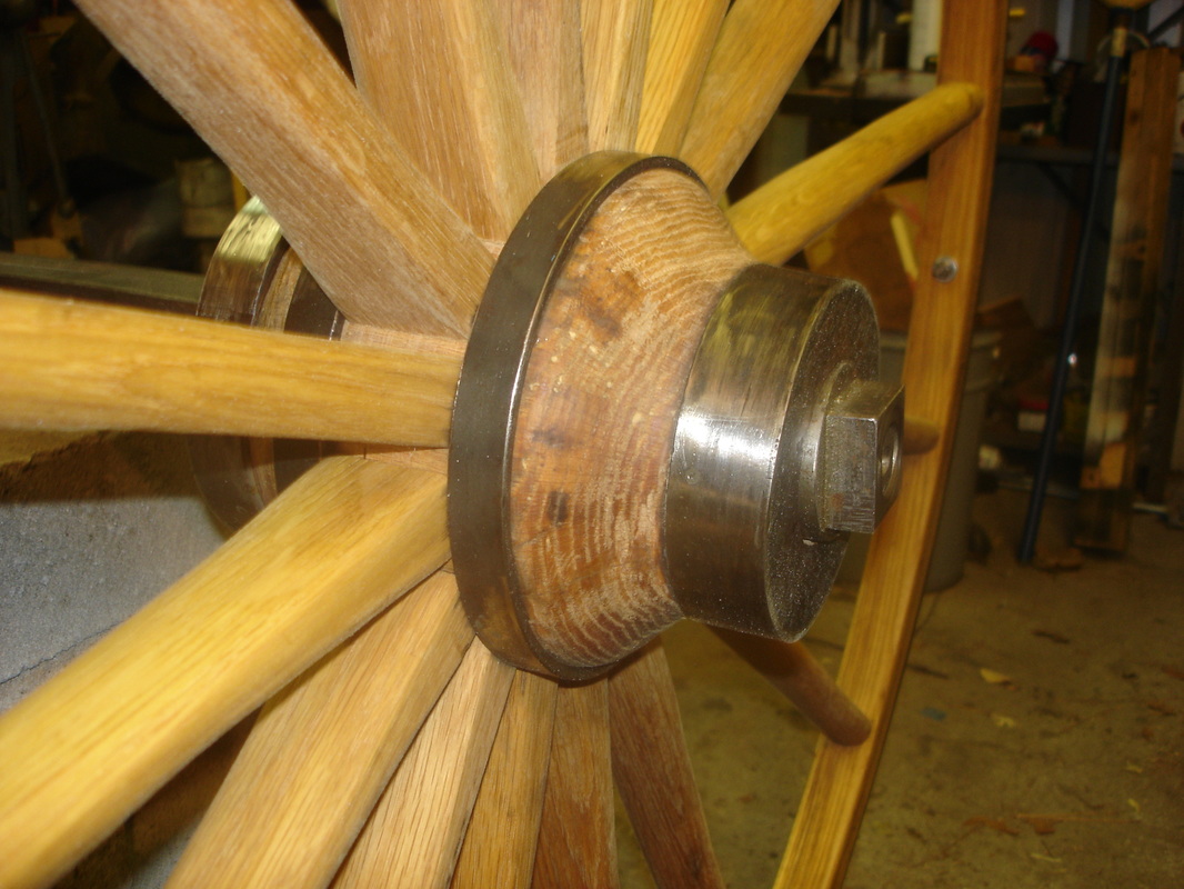
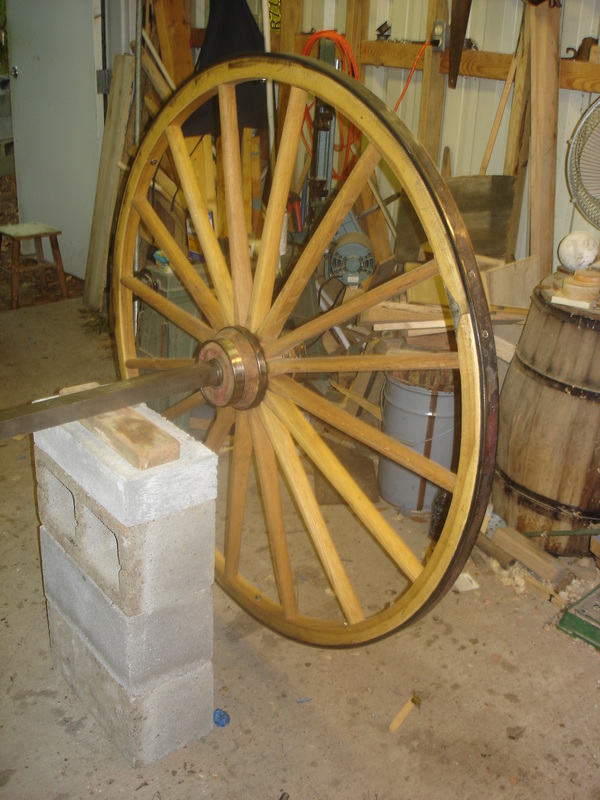
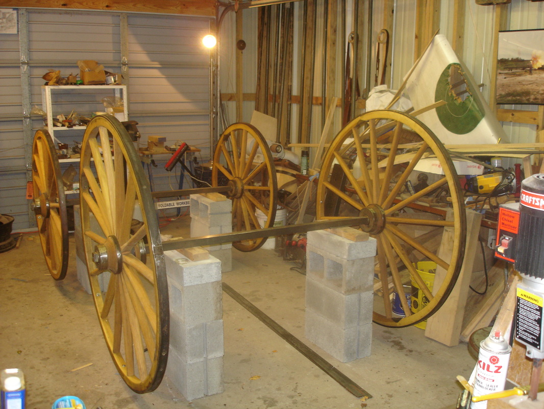
The construction of any horse-drawn vehicle starts with the wheels and axles.
Wheels and axles
Listed below are the contract specifications for the wheels and axles for the ambulance known as the Wheeling pattern taken from the Articles of Agreement by and between Quartermaster for U.S. Army, for and in behalf of the United States and the manufacturer:
HIND WHEELS 4 feet 1 inch high, without tire; hubs 8 inches long by 6-3/4 inches in the center, back of hubs 5-3/8 inches, front 4-1/2 inches; the spokes at shoulder 1-3/4 by 1 inch; felloes 1-5/8 deep by 1-1/2 inch; 16 spokes in wheel felloes in 2 pieces.
FRONT WHEELS 3 feet 5 inches high, without tire; hub felloes and spokes same as hind wheels; 14 spokes in wheels.
TIRE on wheels best refined iron, 3/8 full by 1-1/2 inches, 2 plates on each wheel over the joint of felloe, 8 bolts to fasten each tire on wheel.
AXLES of iron 1-1/2 inches, with nut on each end; axle box 7-1/2 inches long; the track of wheels 5 feet from center to center of wheels.
Photos of the wheels and axles under construction:
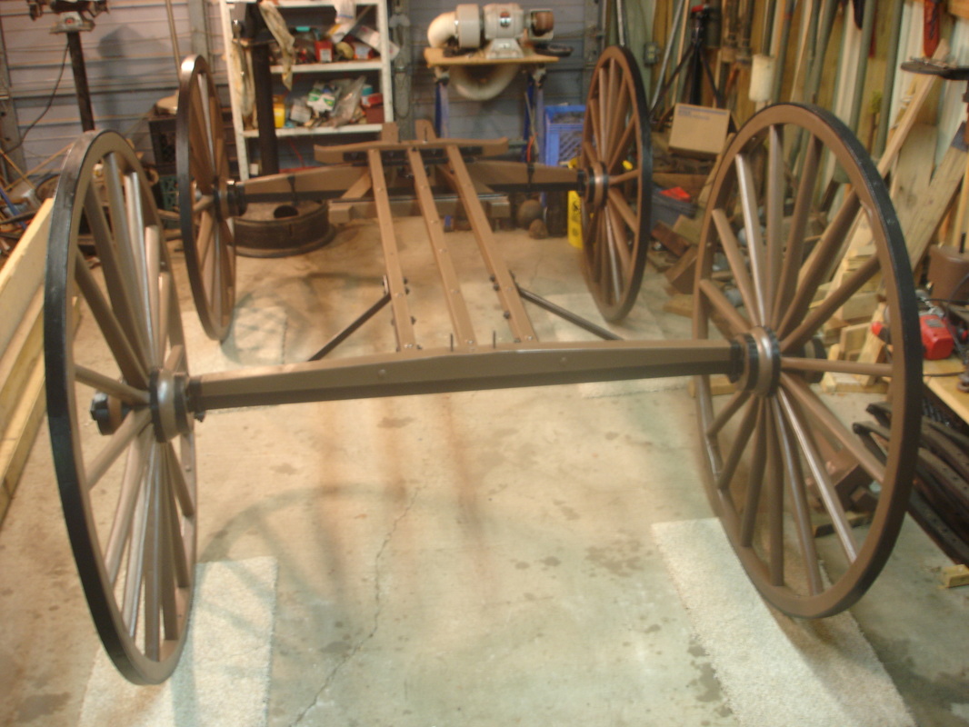
Second posting – September, 2015
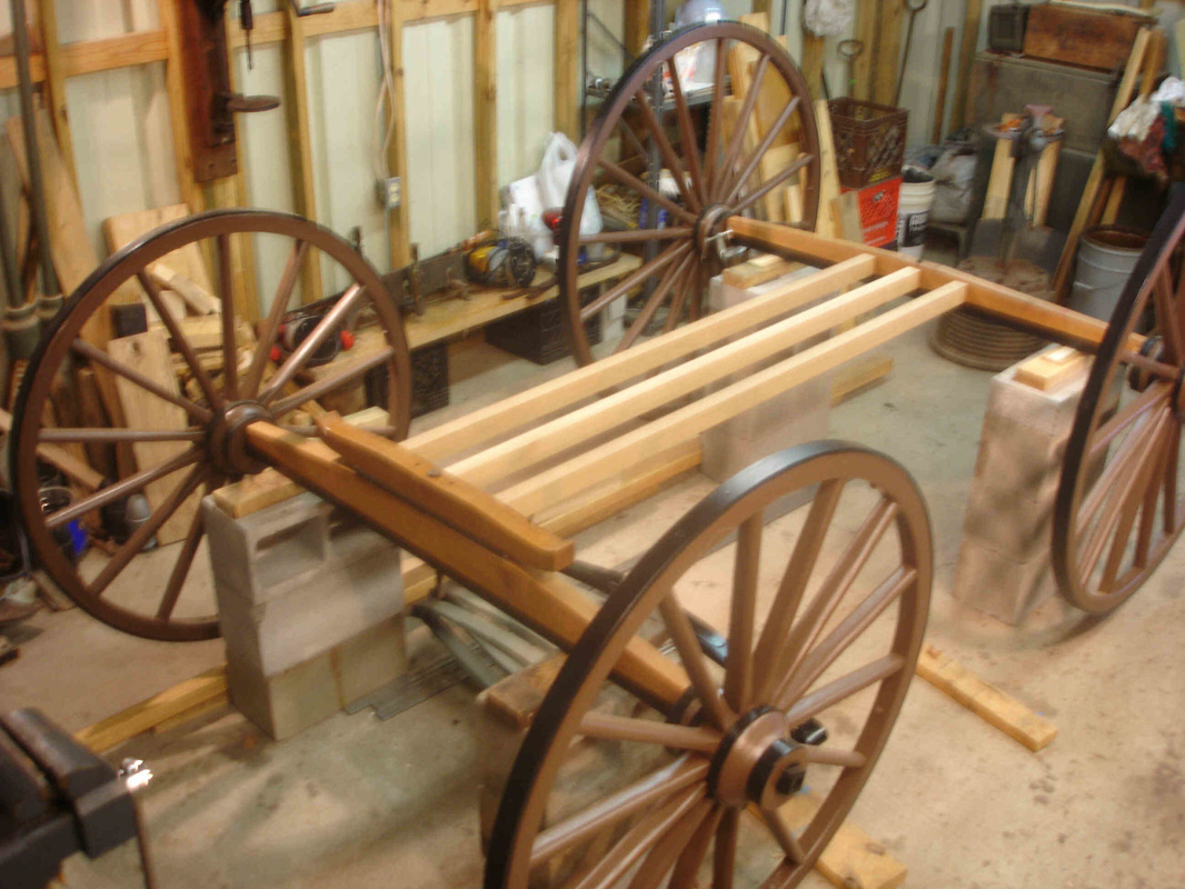
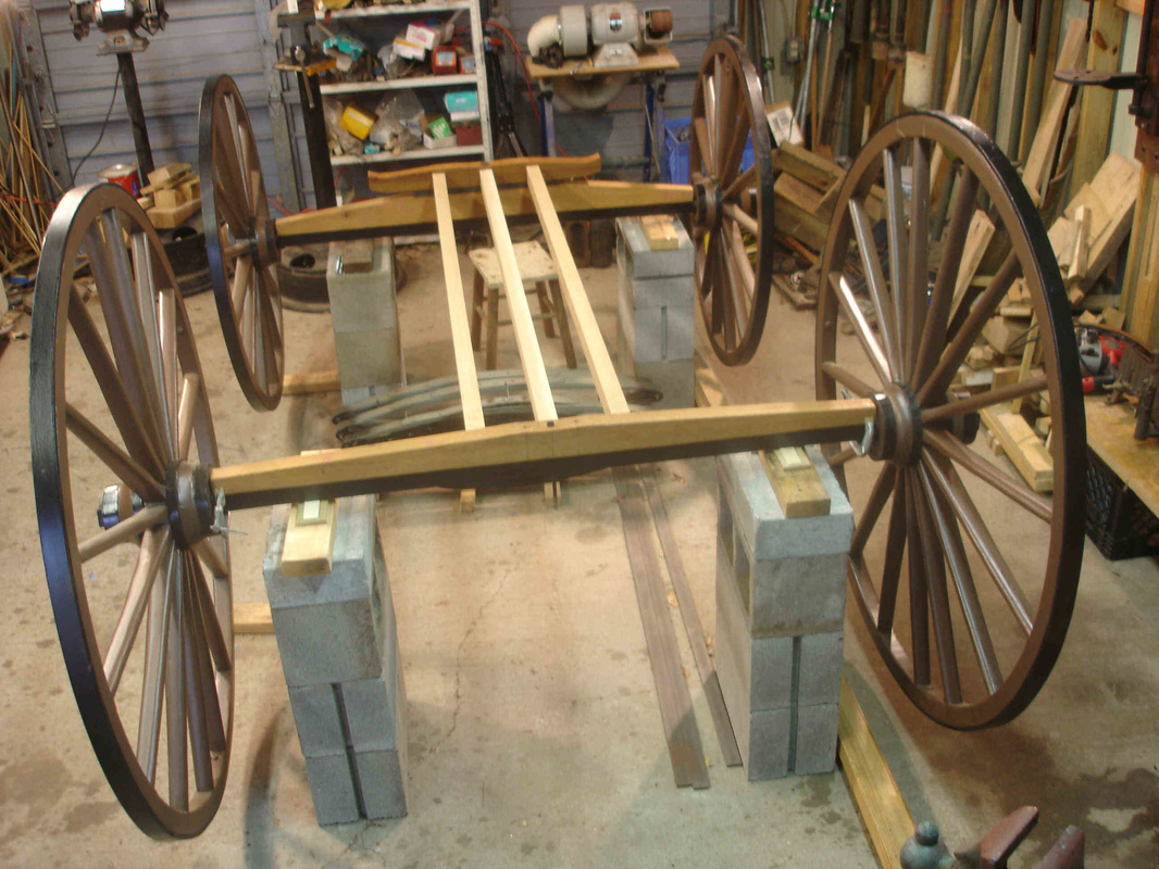
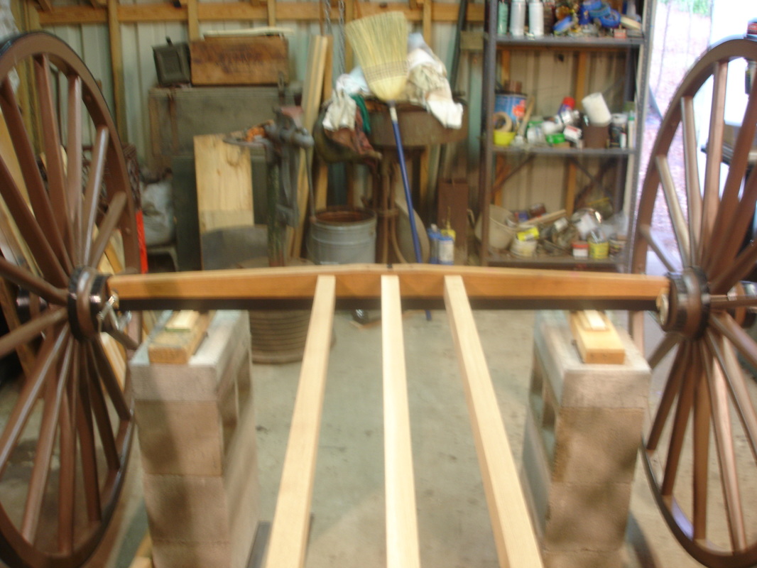
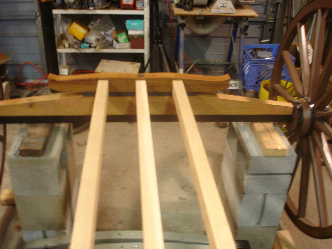
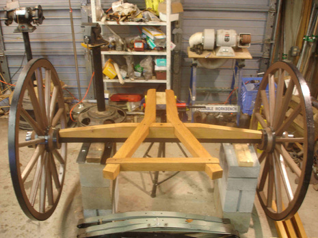
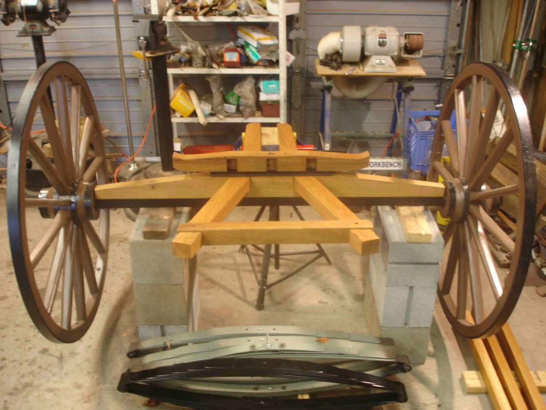
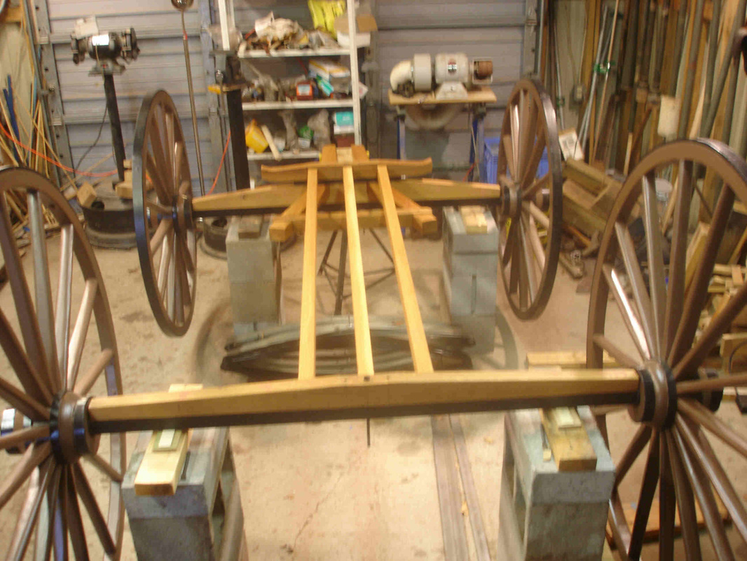
Running gear
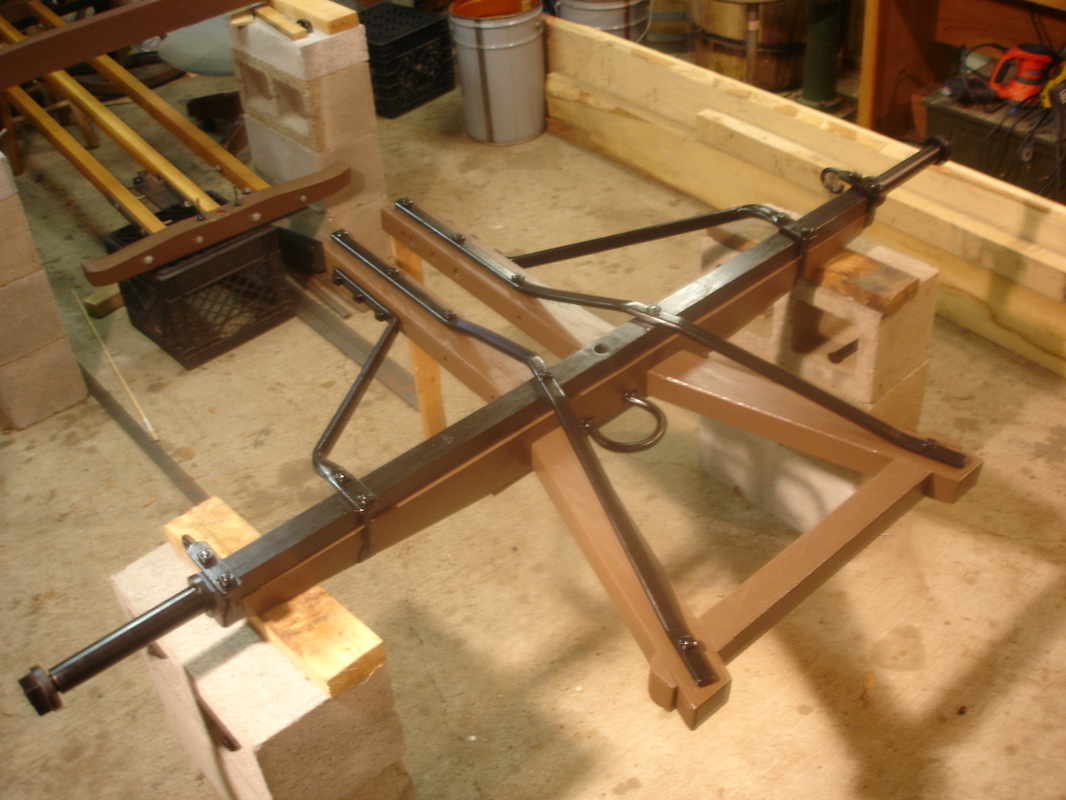
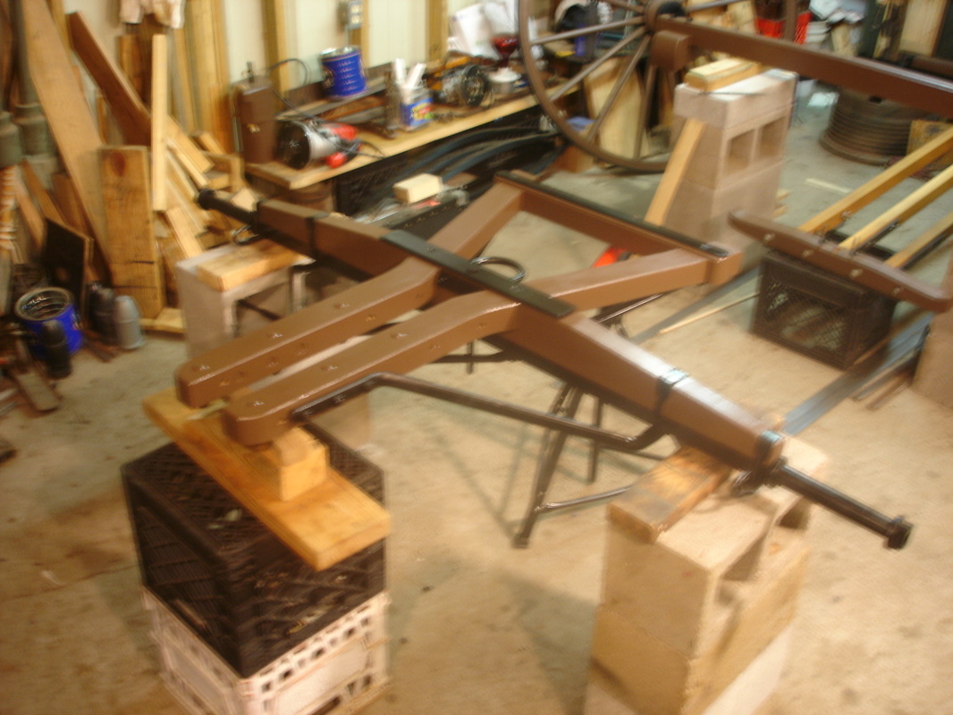
The axle beds, front and back, sit atop the iron axles. Three coupling poles connect the back axle assembly to the head of the spring block. Two iron transit plates, one on top of the front axle bed and the other on the spring block head, act as a fifth wheel and allow the front axle to turn.
Contract specifications for the running gear of the ambulance:
To be made of the best quality of seasoned white oak or hickory.
FRONT AXLE BED 4 feet 6 inches long, 3-1/4 inches deep in center, taper down at ends 1-1/2 inch; 2 inches thick in center, taper down 1-1/2 inch.
BACK AXLE BED 4 feet 6 inches long, 2-1/2 inches deep in center, taper down on end 1-1/2 inch, 1-3/4 wide in center.
3 COUPLING POLES 5 feet 7-1/2 inches long from center of axle bed to center of spring block, 2 inches deep, 1-1/2 wide; to be mortised in axle bed and spring block.
HEAD OF SPRING BLOCK 2 feet 4-1/2 inches long, 2-1/2 inches deep in center, 2 inches wide.
IRON TRANSIT PLATE on top of front axle bed, 18 inches long by 2 inches wide, 3/8 inch deep; iron plate on spring block 18 inches long 2 inches wide, 3/8 inch deep; the plate on axle bed and spring block fastened with 2 countersink bolts each. Iron plate on the bottom of each coupling pole welded to plate on spring block, and extending to back axle to be fastened by axle bolts, and 6 bolts through coupling pole; size of iron plate 1-3/8 wide by 1/4 inch.
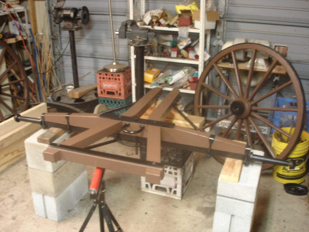
Photos of the running gear under construction:
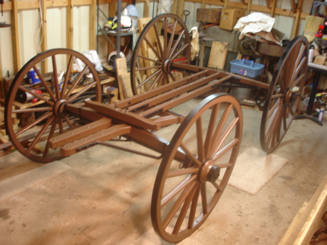
Third posting – October, 2015
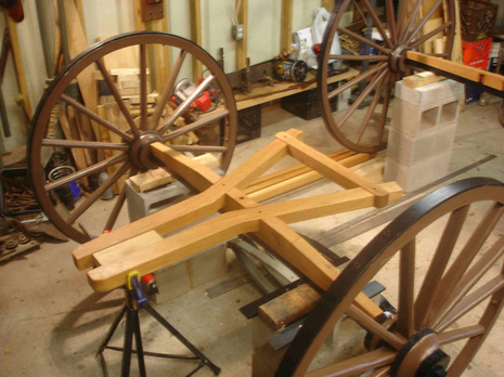
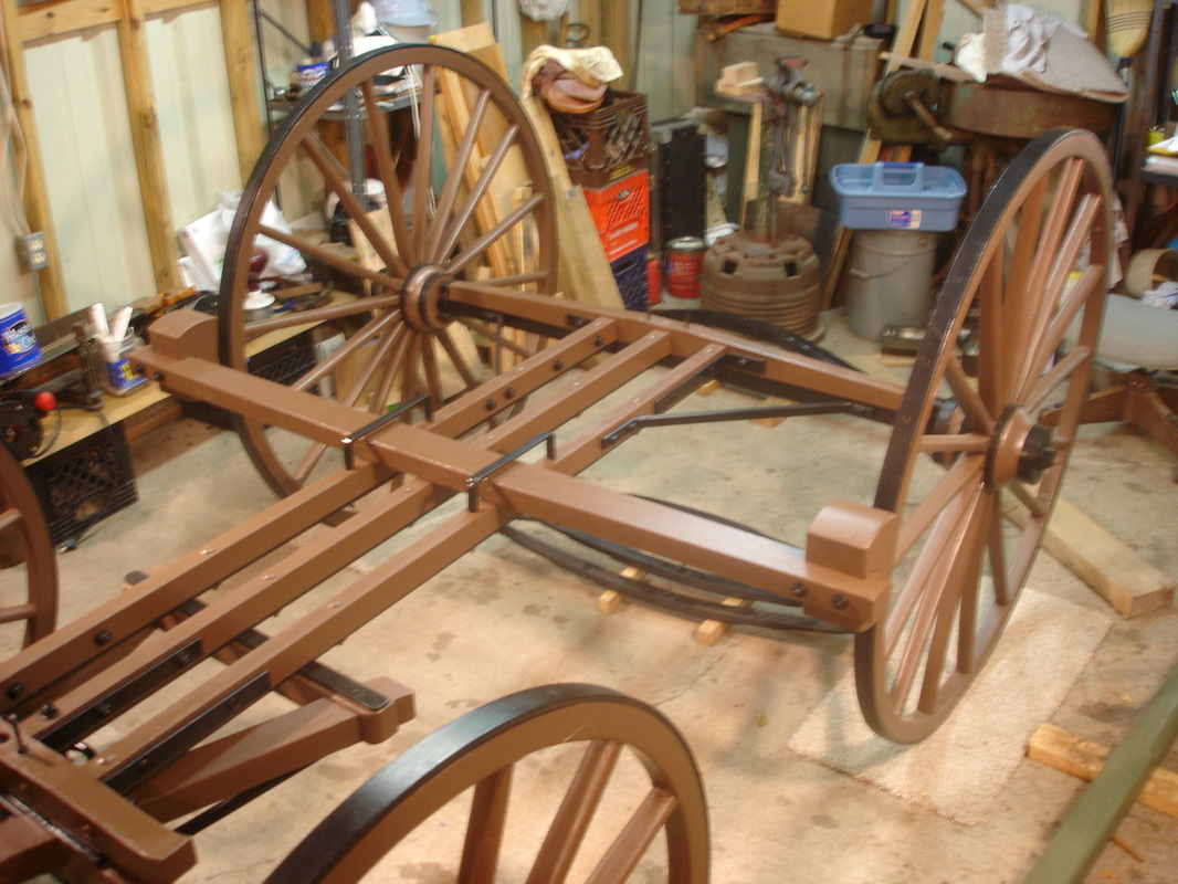
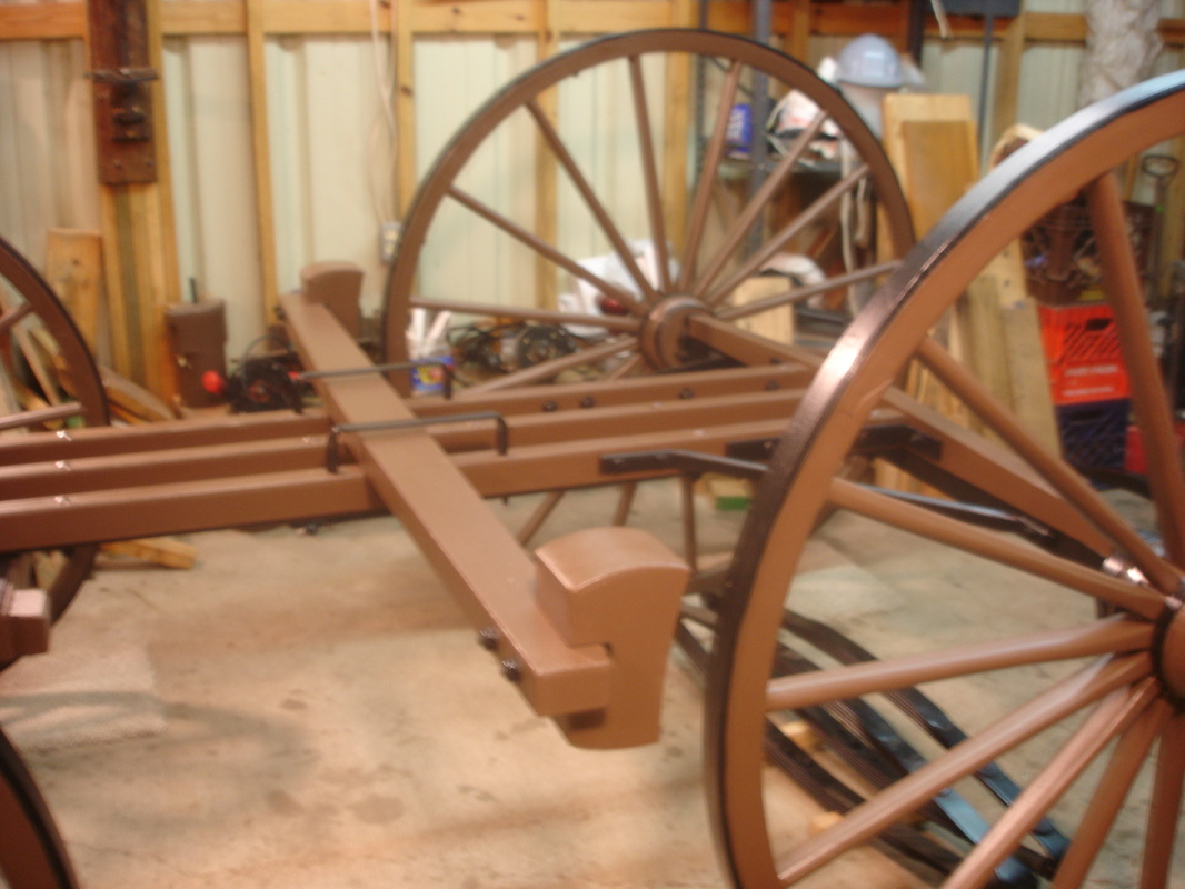
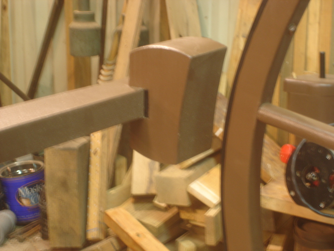
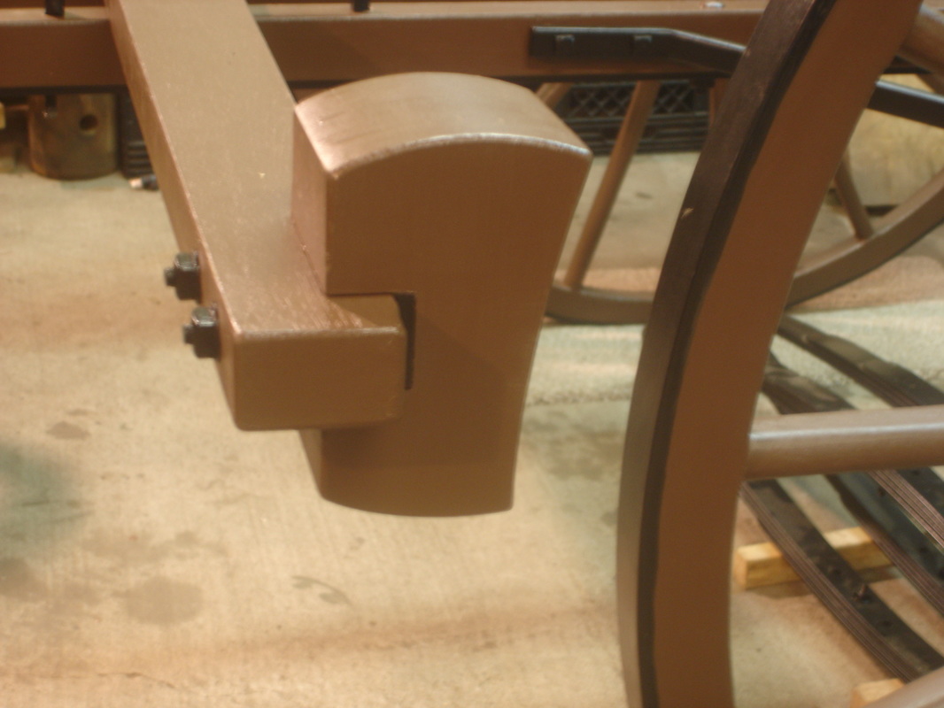
Two hounds and a slider (the steering mechanism)
The hounds and the slider make up the steering mechanism for the ambulance.
Contract specifications for the steering mechanism of the ambulance:
FRONT HOUNDS the whole length from end to end 3 feet 7 inches, 2 deep by 2-1/4 inches wide at axle bed; the jaws of hounds 19 inches long for tongue; length of hounds from center of axle to back slider, 15-1/2 inches; length of slider, 2 feet.
Photos of the steering mechanism under construction:
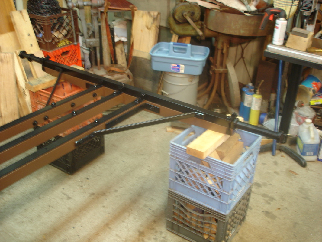
Fourth posting – November, 2015
The end of the woodwork and beginning of the ironwork
The tongue of the ambulance now completes the woodwork for the running gear. The ironwork on the running gear will give support to the woodwork and connects the wood and iron parts into one functioning unit.
A good example of connecting wood and iron is the axle clips which join the wooden axle bed to the iron axle. Another example of joining wooden and iron parts is the iron plates (L-brackets 12” long) connecting the coupling poles to the spring block head.
A few of the components have been painted. The painting scheme for the Wheeling ambulance is as follows: All wood is painted brown and all the iron is painted black. Each side of the body of the ambulance is to be marked U.S. with green paint. Green is one of the colors used to indicate the Medical Dept.
Contract specifications for the wooden tongue and painting of the ambulance:
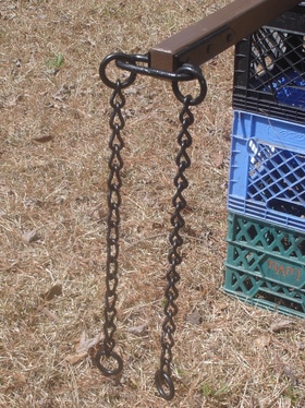
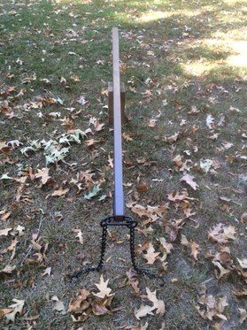
TONGUE 10 feet 11 inches long by 3 inches at front of jaws, tapered down to 2 inches at back end, and tapered down at front end 1-3/4 inches; round ironed the same as omnibus, to be fastened by 3 bolts through jaws of hounds, on end of tongue, 2 breast chains, 1/4 inch iron 2 feet long, with 2 rings in each chain.
PAINTING 2 coats of lead color and 3 coats of brown color paint on body and running gear, striped with green paint; 1 coat of varnish on body and running gear.
Photos of the wooden tongue and the ironwork under construction:
Fifth posting – December, 2015
Oval iron and the front axle
Oval iron is no longer produced in the United States as a stock item so all of the oval iron had to be custom manufactured to accurately reproduce the Wheeling ambulance to the U.S. Quartermaster’s 1862 specifications.
One of the photographs of the front axle is presented upside down so you can observe the 1 inch oval iron stays which extend from the underside of the hounds back to the slider. The photographs of the front axle in the upright position show the 1 inch oval iron stays from the front axle to the side of each hound.
Contract specifications for the oval iron stays of the ambulance:
STAY 1 inch oval iron, to extend from front of hound to back end, under axle, to be fastened with 3 bolts in front part of hounds, and one axle bolt and bolt through the slider.
STAY 1 inch oval iron, from axle to hound, fastened by 3 bolts to each side of hounds.
Photos of the oval iron and front axle:
Sixth posting – January, 2016
The rear axle and more iron work
Some of these photographs are again presented upside down so you can view the extensive iron work of the Wheeling ambulance. In the photos you can observe more L brackets or stays on the side of the coupling poles connecting to the axle bed.
Also visible are the iron plates on the bottom of each coupling pole and additional 1 inch oval iron stays from the side of each outside coupling pole to the rear axle.
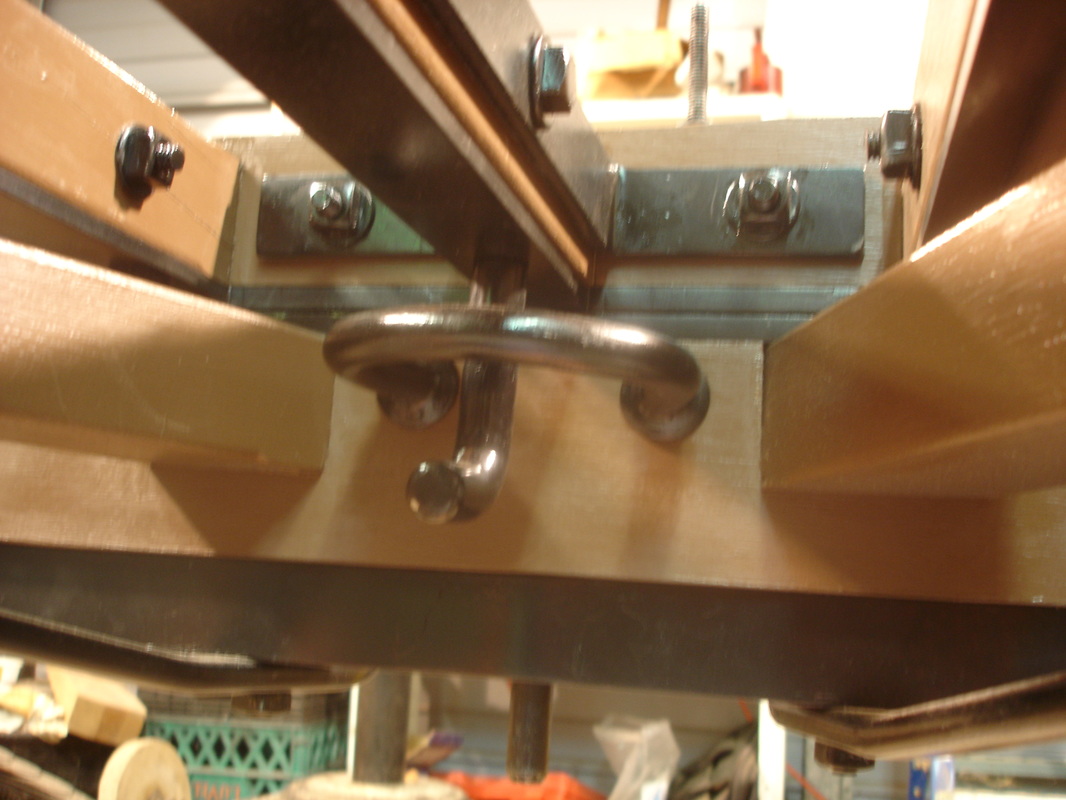
The last photo is of the most unusual aspect of the running gear, the safety hook and guard.
As previously noted in earlier postings all the wood is painted brown and all the iron is painted black.
Contract specifications for the rear axle and more iron work of the ambulance:
On the top of each end of side coupling poles iron stay 12 inches long, extending to the outside of axle bed…
IRON PLATE on the bottom of each coupling pole welded to plate on spring block, and extending to back axle to be fastened by axle bolts, and 6 bolts through coupling pole; size of iron plate 1-3/8 wide by 1/4 inch.
STAY 1 inch oval iron from side of coupling pole to hind axle, fastened by 2 bolts through coupling pole and bolt in axle…
GUARD on front axle bed, with safety hook attached to coupling pole; 2 bolts in axle bed.
Photos of the rear axle and more iron work:
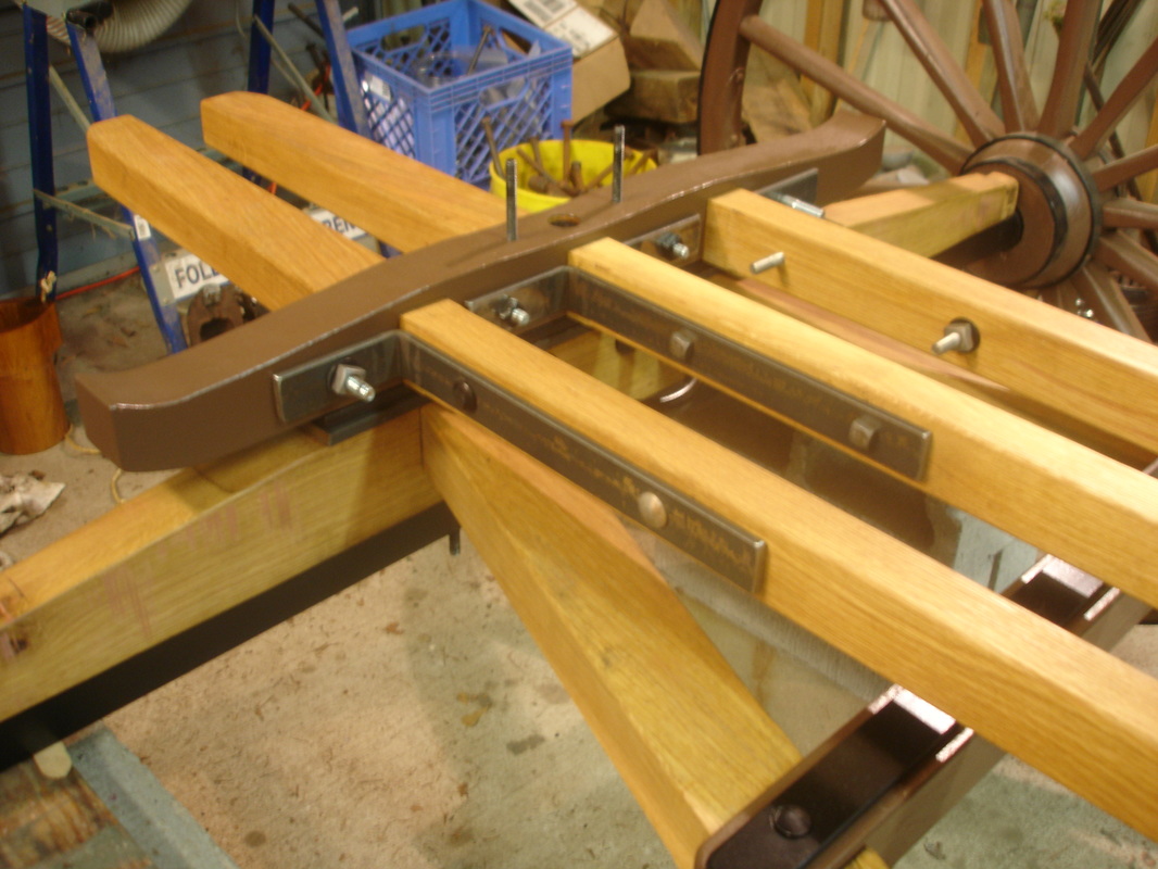
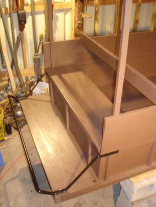
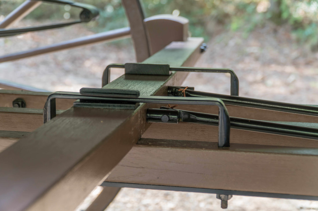
Seventh posting – February, 2016
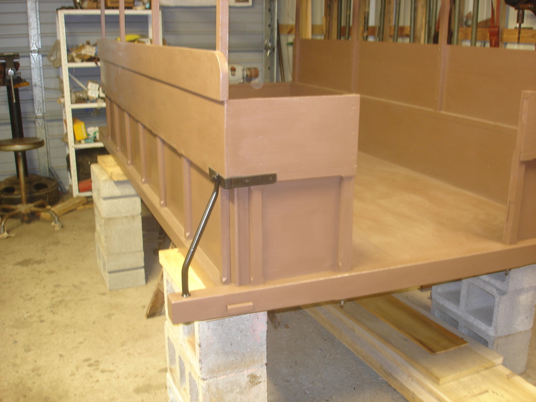
The brake
There is not much to explain about the brake on a vehicle. The brake helps to slow down and stop the ambulance and to prevent it from moving when it is parked.
The lock bar of the brake is engaged by linkage activated by the driver with his foot. The linkage of the brake system will be added later when the body of the ambulance is more developed.
Two staples hold the lock bar in place as it moves forward and back on the coupling poles.
Contract specifications for the brake of the ambulance:
BRAKE OF LOCK BAR 5 feet 8 inches long, 3-1/2 inches wide in center, 1-3/4 inches deep, tapered down to 2-3/4 inches on each end; 2 clamps on end of bar for rub blocks, 4 inches wide by 1-3/4 and 3/8 thick.
2 STAPLES FOR BRAKE BAR, 3/4 oval iron, 8-1/2 inches long, 2 inches deep, fastened by 2 bolts to coupling poles; 2 sliding plates in top of brake bar.
Photos of the brake:
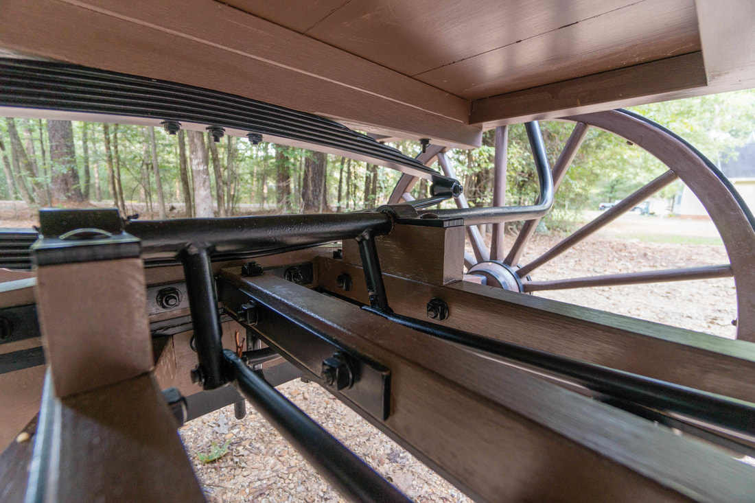
Eighth posting – March, 2016
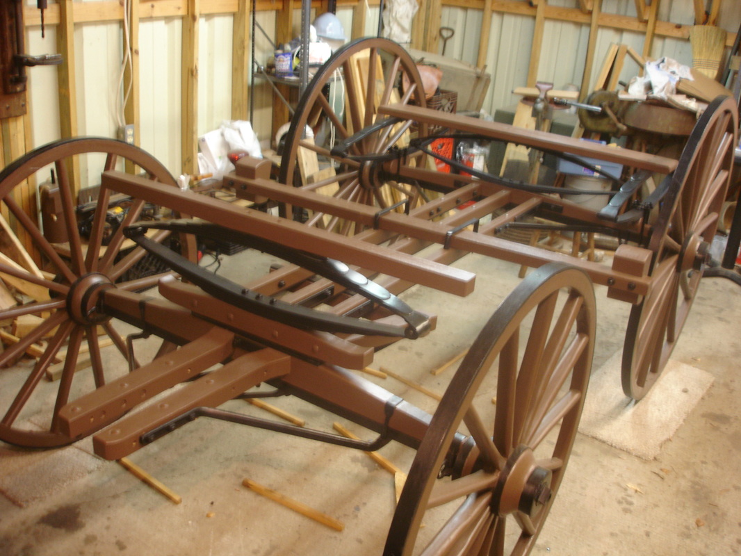
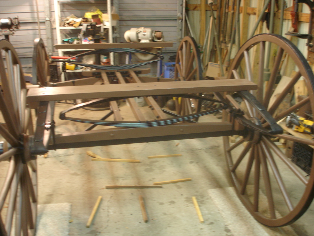
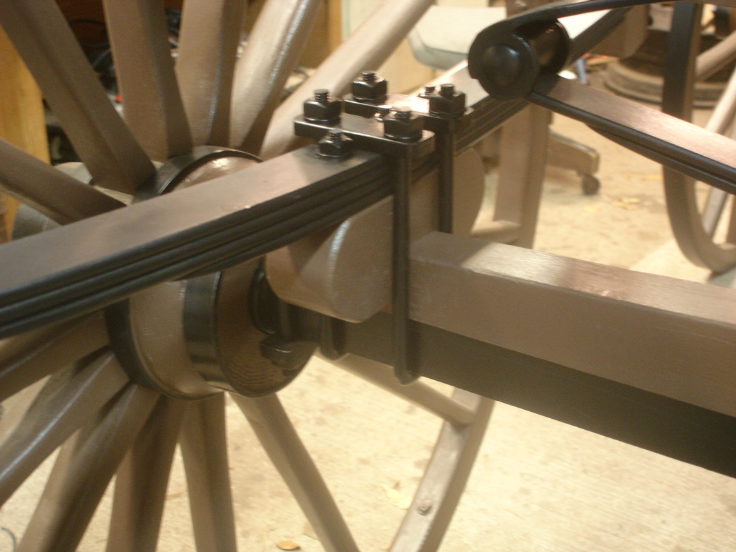
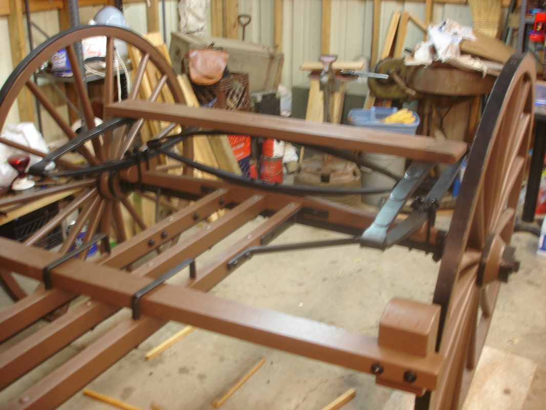
The elliptic springs
The spring suspension system is what made the Civil War period ambulances different from all other previous vehicles or wagons used to transport the sick and wounded. The springs softened the ride over rough terrain which greatly increased the likelihood of survival for the occupants of the ambulance. Now that the springs have been installed the running gear is now completed.
The next step in the process of building the Wheeling ambulance is to start construction of the ambulance body.
Contract specifications for the elliptic springs of the ambulance:
FRONT SPRING, 3 feet 3 inches long, 2 inches wide; 6 plates, fastened with 2 bolts through head or spring block, and 2 bolts through spring bar, one cross spring on back axle bed, 3 feet 3 inches long, 1-1/2 wide; 4 plates, fastened on by 2 bolts through axle and axle bed.
2 back SIDE SPRINGS, 3 feet 3 inches long, 1-3/4 inches wide; 4 plates, fastened with 2 clips and 2 couplings each, with flat plate iron on top of spring plate to prevent the coupling from closing, and 2 bolts each, through spring bar; the best quality of spring steel.
Photos of the elliptic springs:
Ninth posting – April, 2016
Body of the ambulance
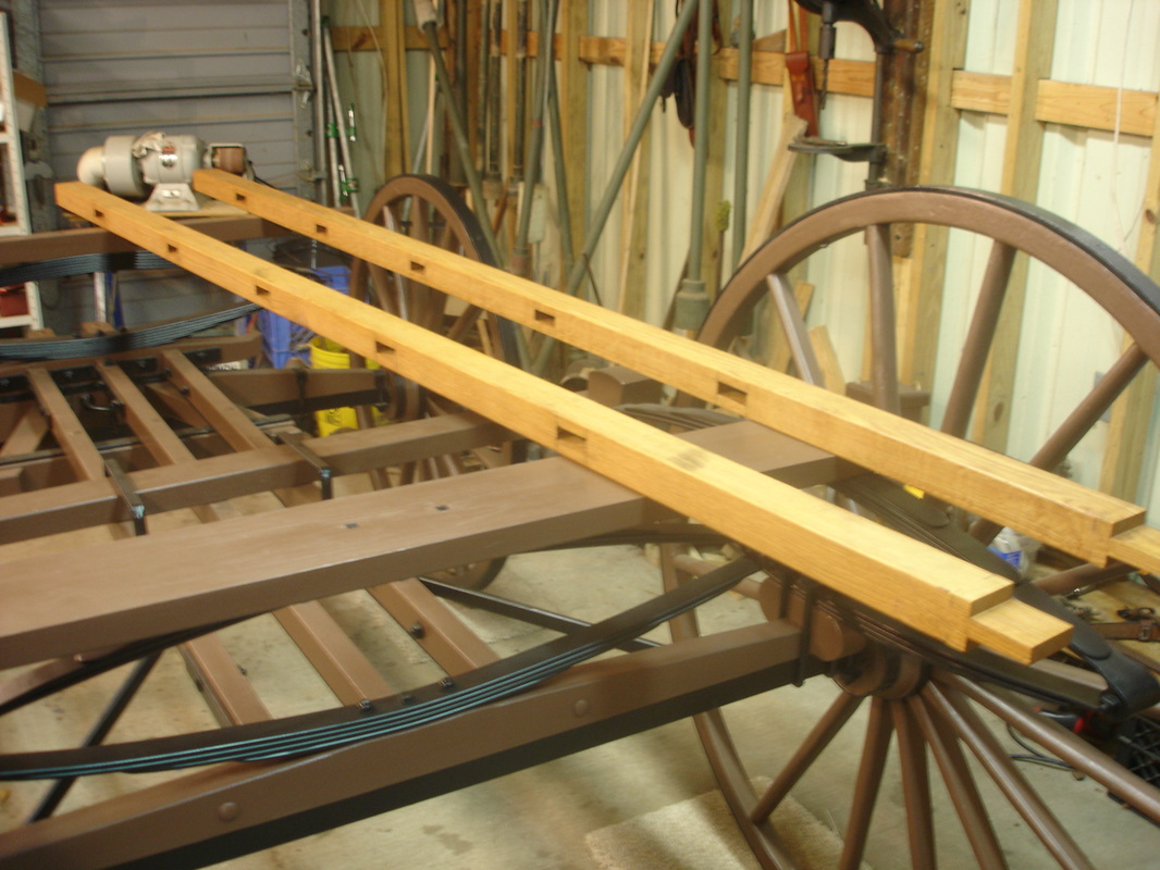
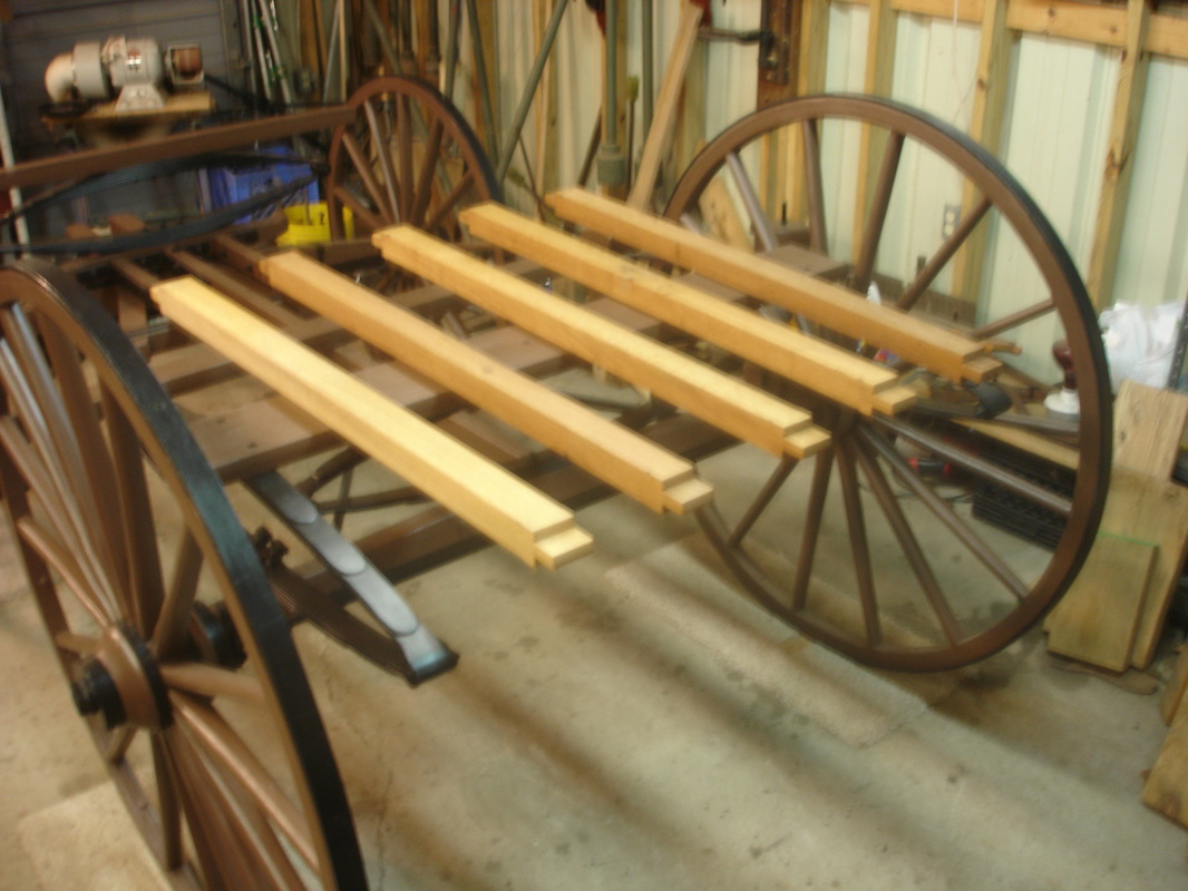
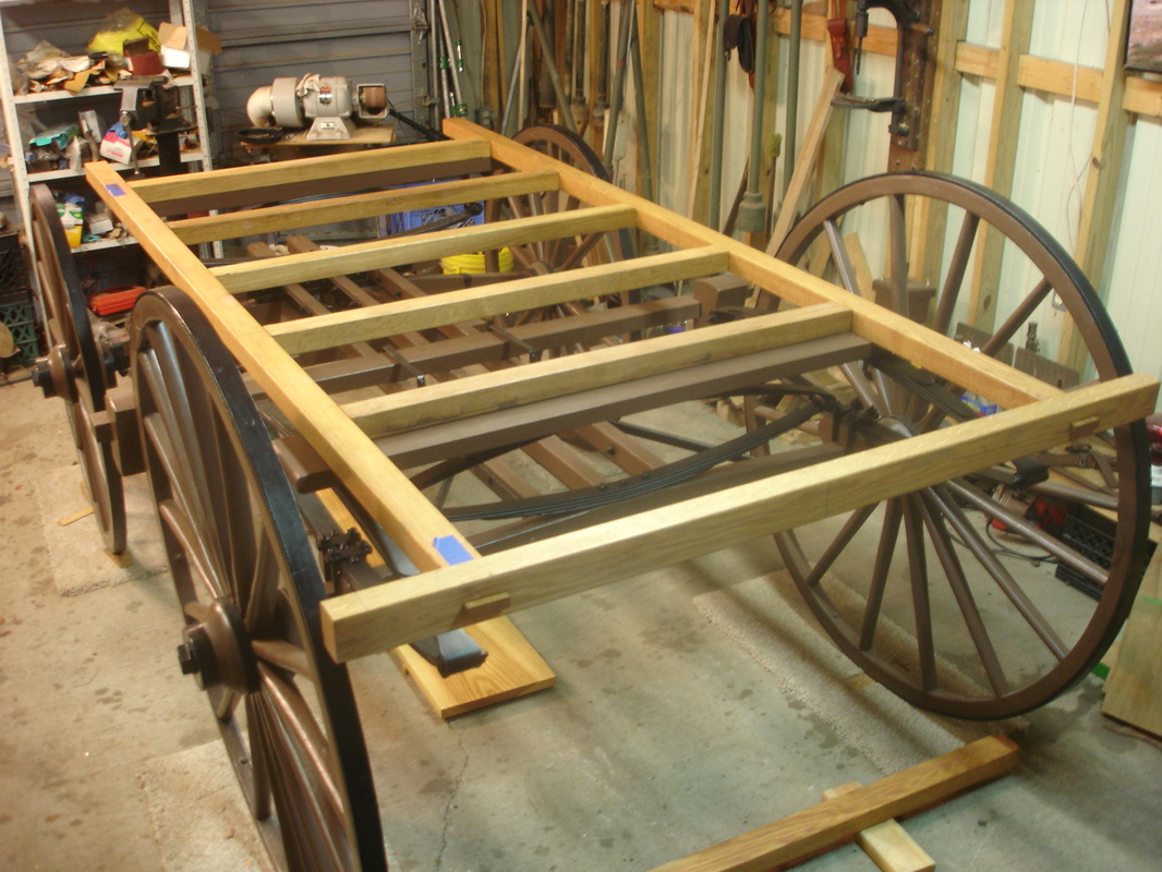
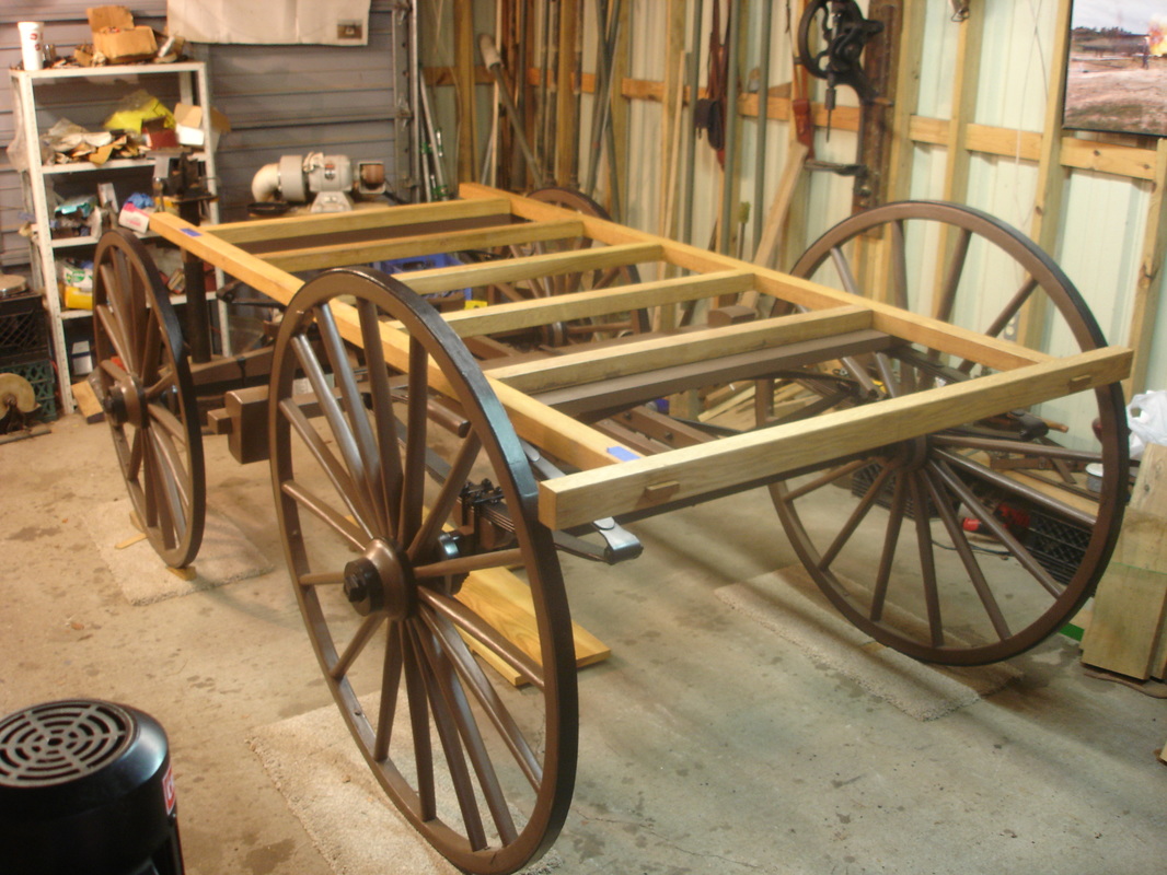
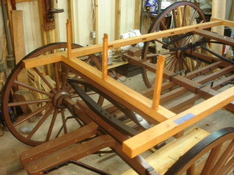
With the running gear completed I have now started construction on the body of the ambulance. The build begins with the frame of the body. The two sills (the long outside pieces) and the six cross bars (the short pieces) make up the frame which will eventually be bolted to the running gear.
Contract specifications for the body of the ambulance:
SILLS 8 feet 6 inches long, out to out (including foot board), 2-1/2 inches wide by 2 inches deep.
6 CROSS BARS in frame of body, front bar 2-1/2inches wide by 2 inches deep, middle bars 2-1/4 inches wide by 2 inches deep, back bar 2-3/4 inches deep by 2 inches wide with iron brace to stud, with body 4 feet wide from out to out.
Photos of the ambulance body:
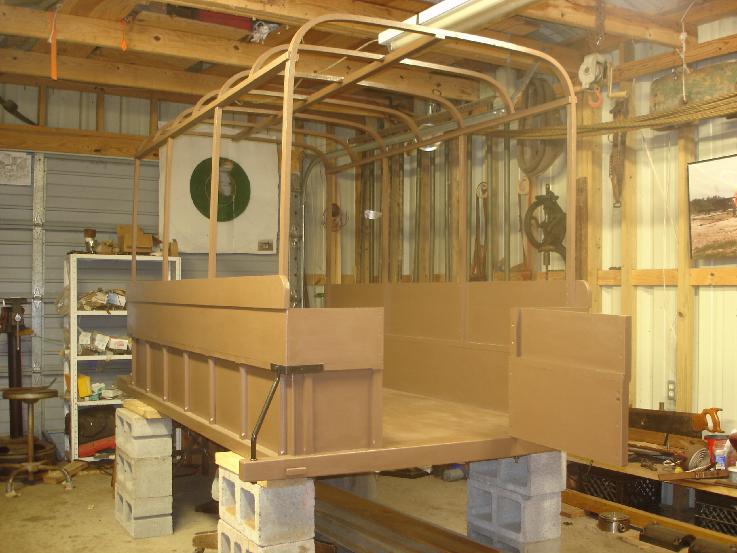
Tenth posting – May, 2016
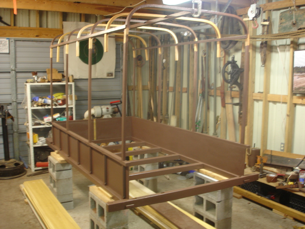
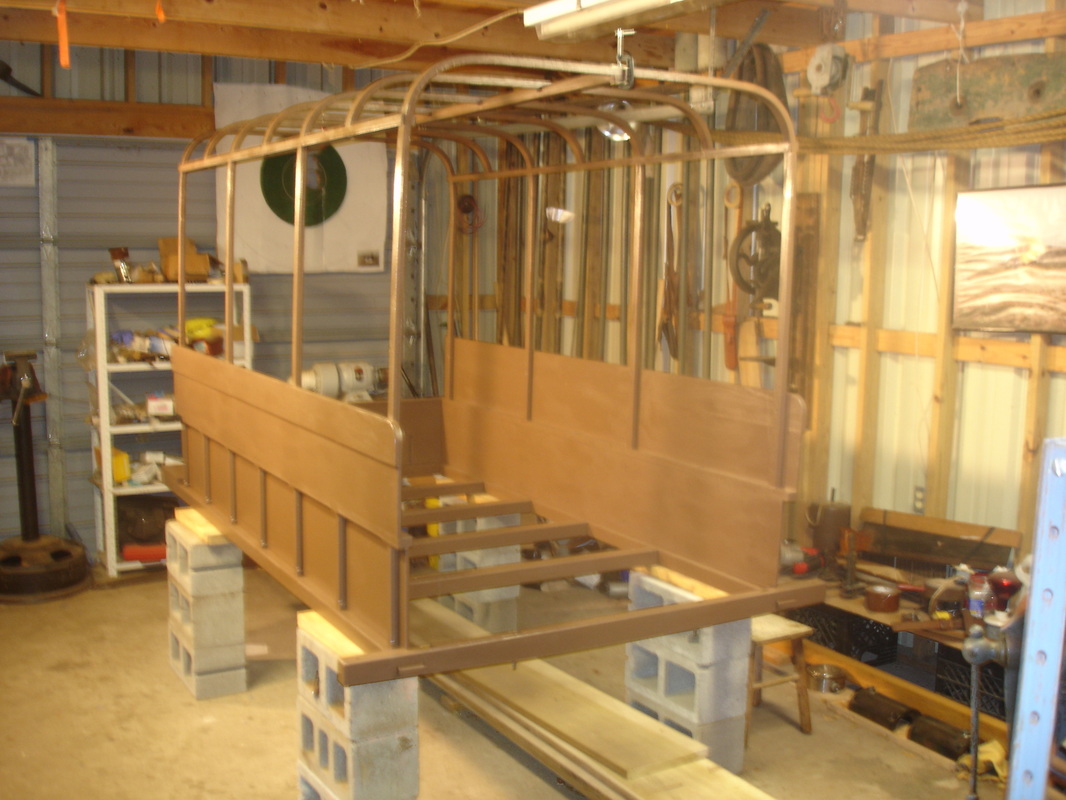
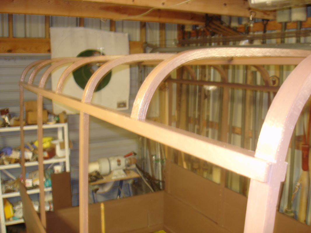
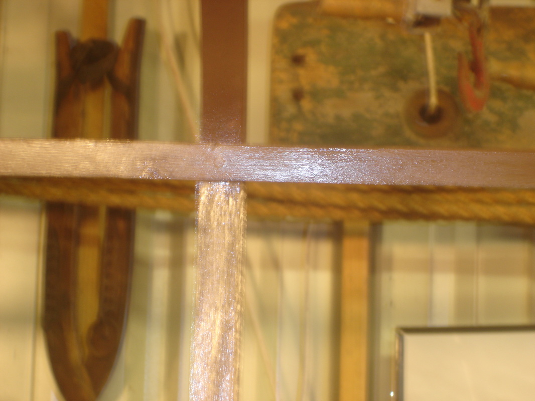
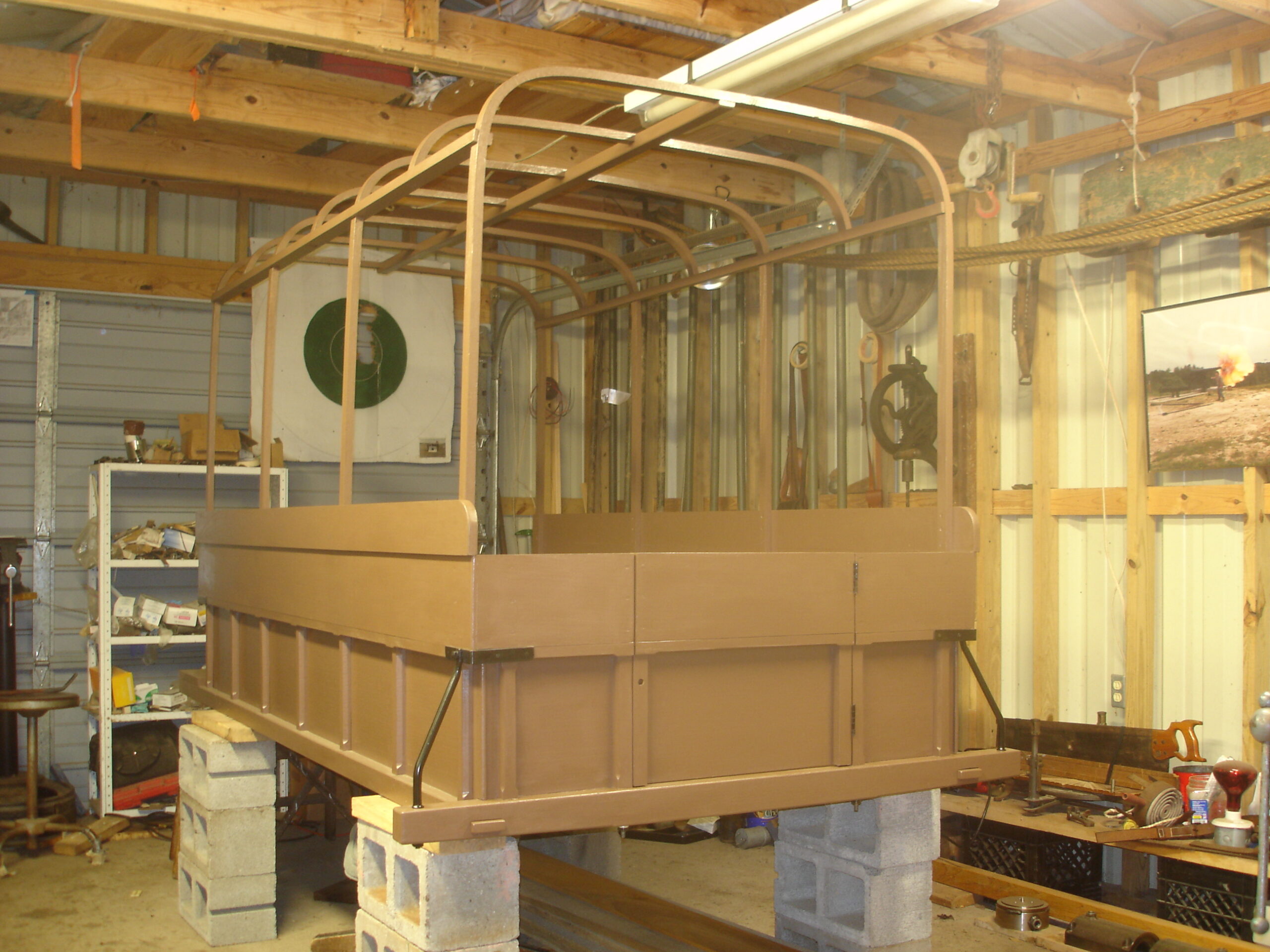
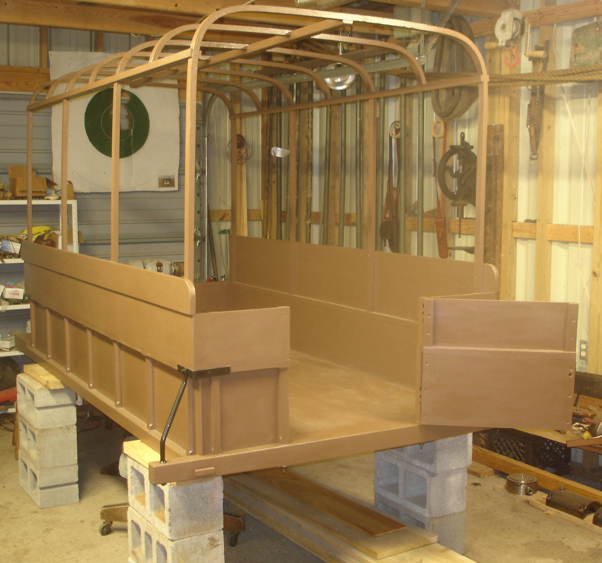
Bows, studs, and rails
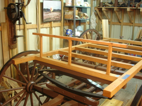
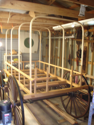
The bows, studs, and middle rails make up the skeleton or framework for the body of the ambulance. The panels or sides of the ambulance will be attached to the bows and studs. Both the bows and studs are mortised through the middle rails.
Contract specifications for the bows, studs, and rails of the ambulance:
4 BOWS 1-1/4 inches wide by 3/4; top 4 feet 6 inches high from inside of bottom to top of ridgepole.
The 4 bows mortised in sills of body make part of the 7 studs; the STUDS 13 inches high, 1-1/4 inches wide, 3/4 thick, middle RAIL 1-1/2 inches wide, 1 inch deep.
Photos of the bows, studs, and rails:

Eleventh posting – June, 2016
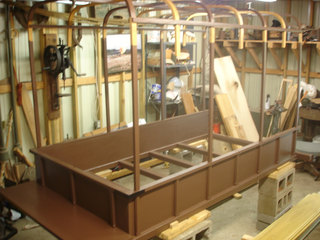
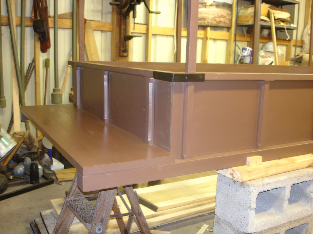
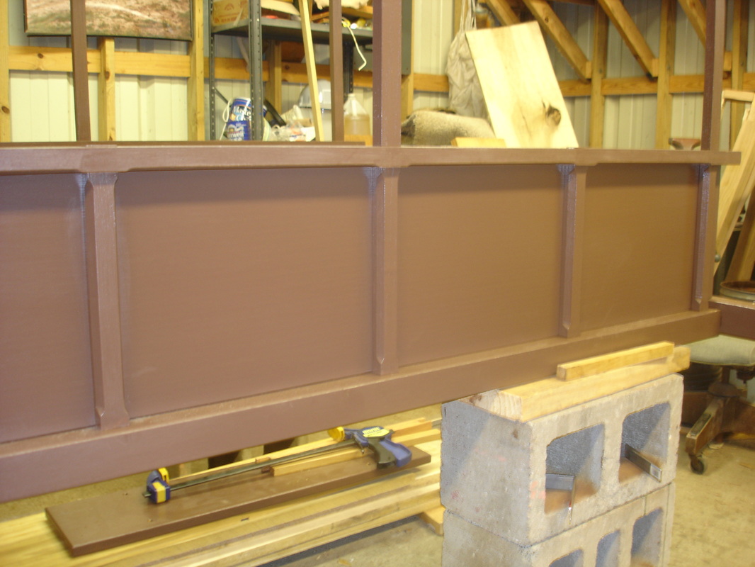
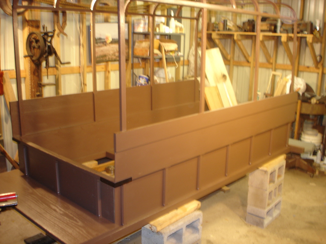
Side panels
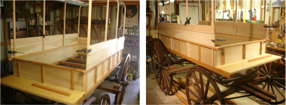
Both sides of the ambulance are made up of three separate panels – the lower, middle and top panel. The panels will be attached with cut nails and No. 10 wood screws.
Contract specifications for the side panels of the ambulance:
The LOWER PANEL poplar, 10-1/2 inches wide by 3/8; the second or MIDDLE PANEL poplar, 6-3/4 inches wide by 3/8, the TOP PANEL ash, 4 inches wide by 3/4. Depth of body from out to out 23-1/2.
Photos of the side panels:
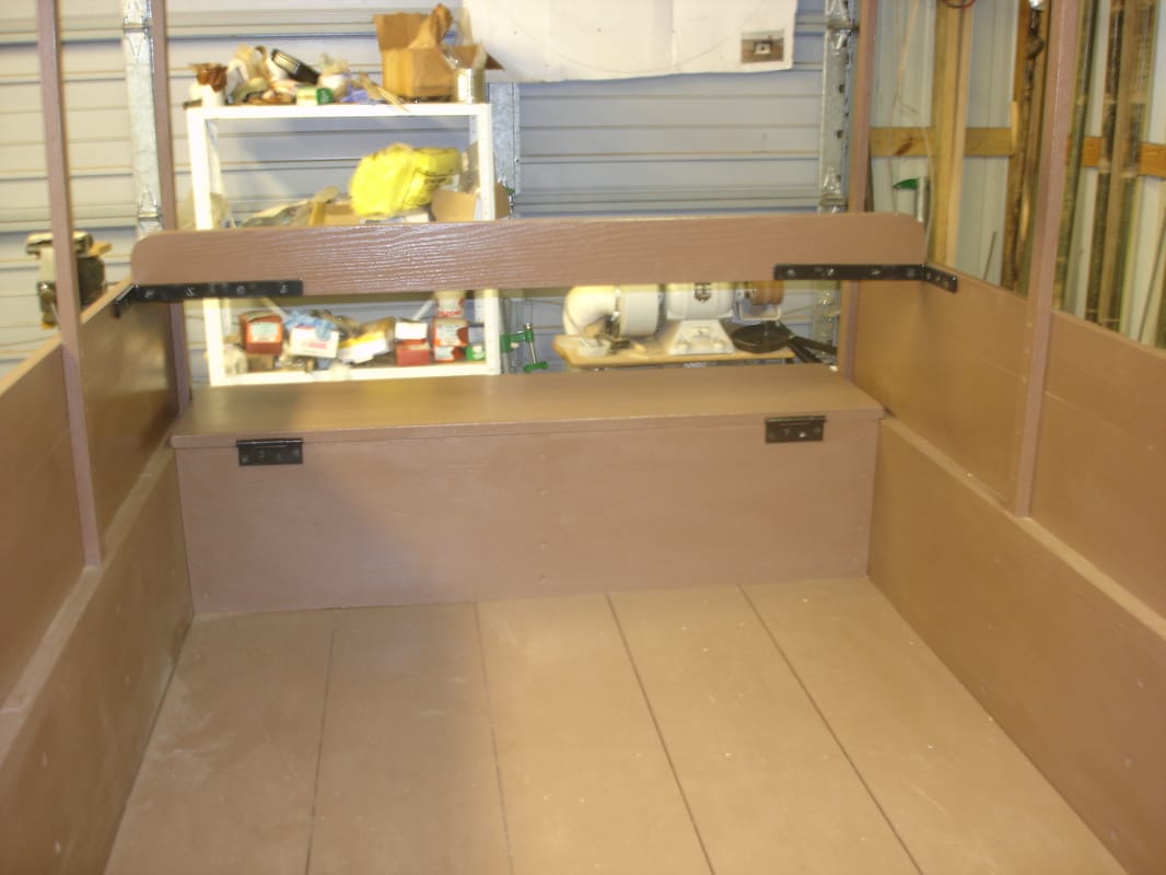
Twelfth posting – July, 2016
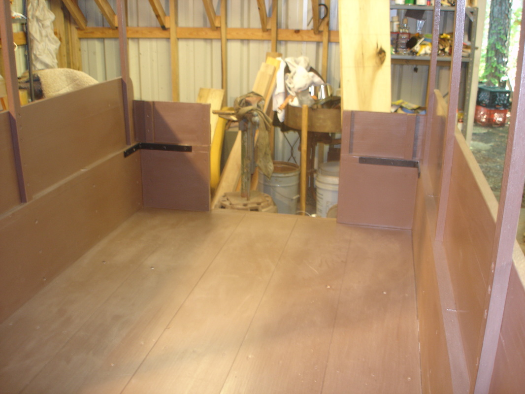
Floor and back board (step)
I have disassembled the sides (top and middle panels) to allow for more room to work on the floor of the ambulance and the back board or step. The step is needed to allow entrance into the vehicle and assist the stretcher bearers when loading and unloading the sick and wounded.
Contract specifications for the floor and back board of the ambulance:
Bottom of body (FLOOR) 1/2 inch pine boards, planed.
BACK BOARD 8 inches wide, 3 feet long, 1 inch ash stuff; 4 heavy stay irons from back of body to back board 2 feet long.
Photos of the floor and back board (step):
Thirteenth posting – August, 2016
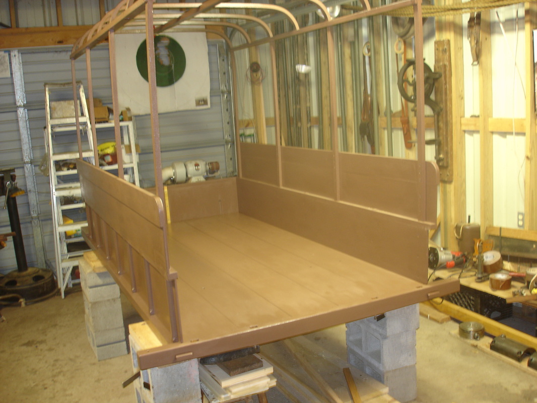
Final assembly: lower panels
With this posting my journey to complete a Civil War Wheeling ambulance has now progressed for one year. When I started the project I hoped to build the running gear in the first year which I have done. The second year of the project has now begun and I hope to finish the body of the ambulance in this second year. Time will tell if I can finish my journey to completion by August 2017 or not.
I have dismantled the ambulance, painted all the individual parts with two coats of oil base brown paint and now I am reassembling the vehicle. In this final assembly all tenons will have wooden pegs going through them to permanently hold the vehicle together.
Looking at the current photos you will notice that I have removed the running gear or undercarriage. The ambulance was getting too tall to take out of the shop door in one piece. Now the body of the ambulance will be completed, then taken out of the shop and reunited with the running gear.
In the photos you can observe not only the lower rails, studs and bows but also the center ridge pole, curtain rails and ribs (short bows). The sides of the ambulance have three panels – lower, middle and top. You are looking at the lower panels which are attached with No.10 wood screws from the inside of the body. Also, you can see the iron corner bracket which is painted black on the front end of the lower rail. All four corners will have a bracket.
To those of you who have been following my progress, I hope you enjoy watching the progress of the ambulance as much as I enjoy building it and sharing it with you. Let the journey continue.
Contract specifications for the corner plates of the ambulance:
4 CORNER PLATES on rail of body, 1 inch wide with 4 inch legs.
The specifications for the PANELS were listed in the eleventh posting – June, 2016.
Photos of the lower panels:
Fourteenth posting – September, 2016
Final assembly: middle and top panels
Now that the middle and top panels have been attached to the bows and studs with cut nails and No.10 slotted wood screws both sides of the ambulance body are now completed. In the attached photos you will also notice the ribs or short bows in the top of the vehicle have been cut to length and painted. All of the bows and ribs now have wooden pegs going through them where they meet the curtain rail.
Contract specifications for the middle and top panels of the ambulance:
The specifications for the MIDDLE and TOP PANELS were listed in the eleventh posting – June, 2016.
The specifications for the BOWS were listed in the tenth posting – May, 2016.
Photos of the middle and top panels:
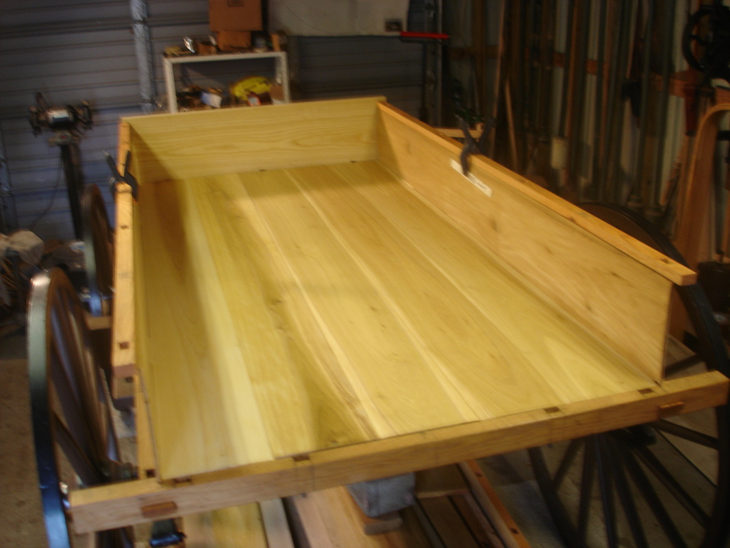
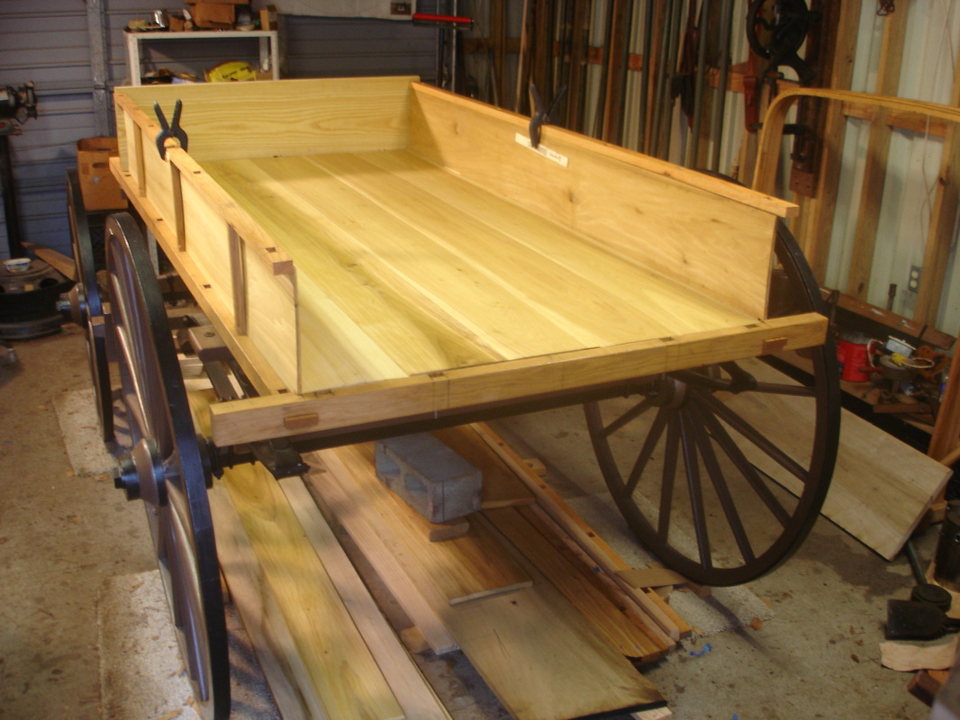
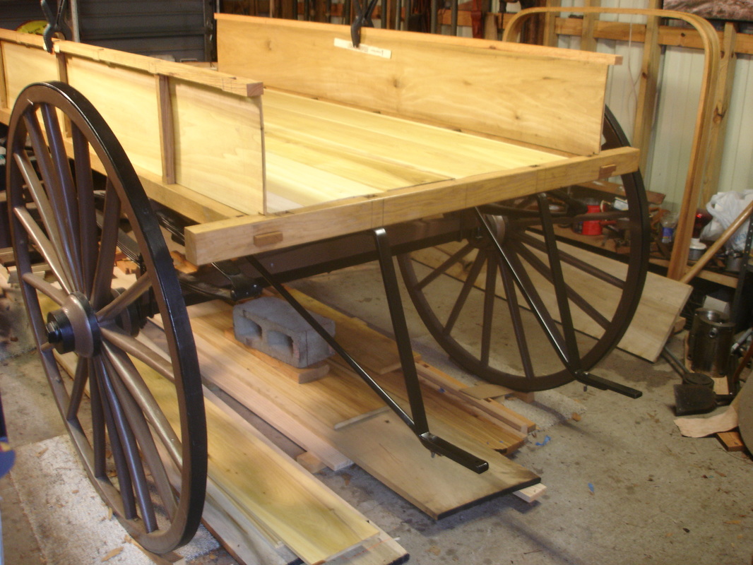
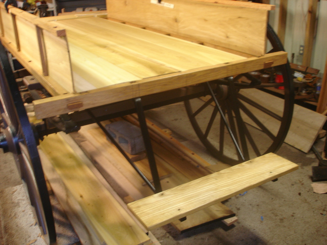
Fifteenth posting – October, 2016
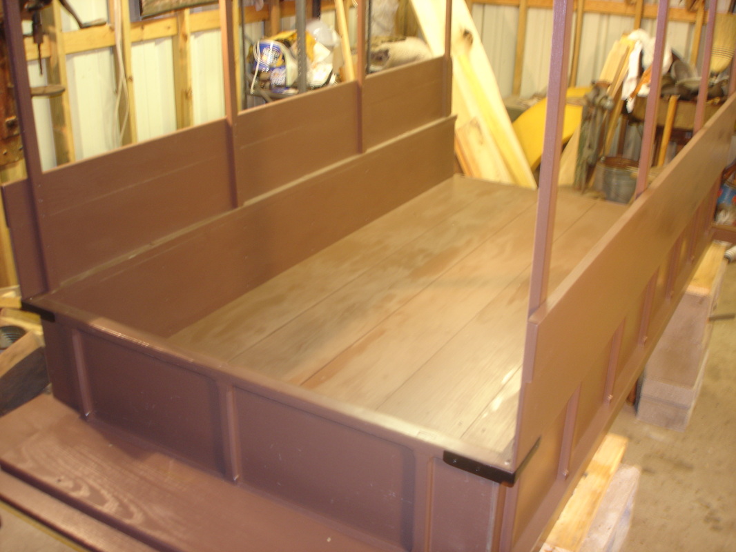
Final assembly: floor boards
Now that the floor boards are in place and painted you can see the ambulance body taking shape. The boards are attached with cut nails. Contract specifications for the floor boards are listed in the twelfth posting – July, 2016.
In the photos you can see the ridgepole running down the center of the top of the ambulance. Also visible in the photos are the two curtain rails, one on each side, which along with the ridgepole help connect all the ribs and bows. Specifications for the curtain rails are the same as the middle rail listed in the tenth posting – May, 2016.
The contract does not give dimensions for the ridgepole. I made the ridgepole 2 inches sq. with notches cut on the top to accept ribs and bows.
Contract specifications for the height of the ridgepole and curtain rails of the ambulance:
4 feet 6 inches high from inside of bottom to top of RIDGEPOLE, from top of upper panel to CURTAIN RAIL 2 feet 3 inches.
Photos of the floor boards:
Sixteenth posting – November, 2016
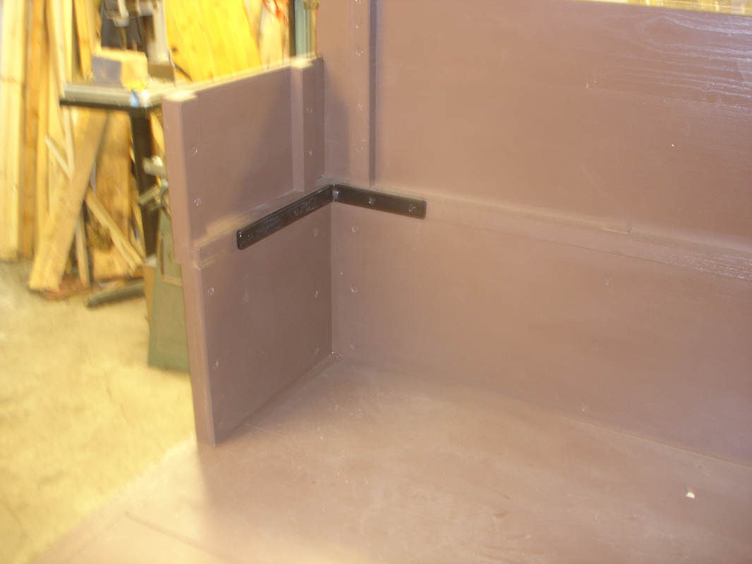
Final assembly: rear end panels
The photos in this posting show the rear end panels of the ambulance. Notice the iron plates inside and outside of the corners. They are painted black. Also, you can see the iron brace from the rear cross bar connecting to the middle rail or stud. Remember all of the iron is painted black and all of the wood is painted brown.
Contract specifications for outside and inside corner plates plus the iron braces of the ambulance:
Back bar 2-3/4 inches deep by 2 inches wide with IRON BRACE to stud.
2 heavy iron CORNER PLATES to be fastened by 10 screws, No. 10.
4 CORNER PLATES on rail of body.
The specifications for the outside CORNER PLATES were listed in the thirteenth posting – August, 2016.
Photos of the rear end panels:
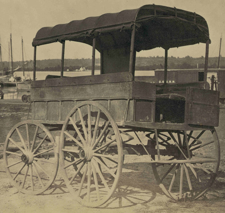
Seventeenth posting – December, 2016
The back door
The back end of the ambulance now has a door. The 1/2 inch hole on the left side of the door is where the handle for the door will be located.
For a comparison of back doors I am showing you side by side photos of my Wheeling and a Civil War Wheeling ambulance.
Contract specifications for the back door of the ambulance:
DOOR in back of body 21 inches wide, 17-1/2 inches deep, with 2 strap hinges on stud, with door lock and silver-plated handle.
Photos of the back door:
Eighteenth posting – January, 2017
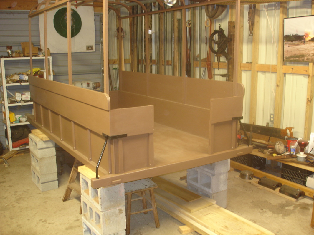
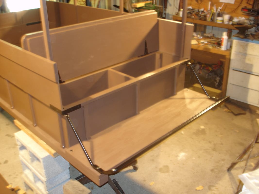
Final assembly: front end
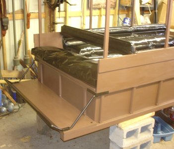
In this posting you will see the ambulance driver’s seat, the foot rail, two stay irons (one on each corner), and the back support bar which is called a lazy back. The driver’s seat will have a black oil cloth covered cushion stuffed with curled horse hair. The lazy back will be upholstered with black oil cloth and also stuffed with horse hair.
The box under the driver’s seat is divided into two equal compartments.
Contract specifications for the front end of the ambulance body:
A box in front of body 11-1/4 inches deep, 12-1/2 wide, with lid and hinges; lazy back covered with oil cloth and stuffed with curled hair, fastened to side rails.
3 heavy STAY IRONS on front foot board.
Photos of the front end of the ambulance body:
Nineteenth posting – February, 2017
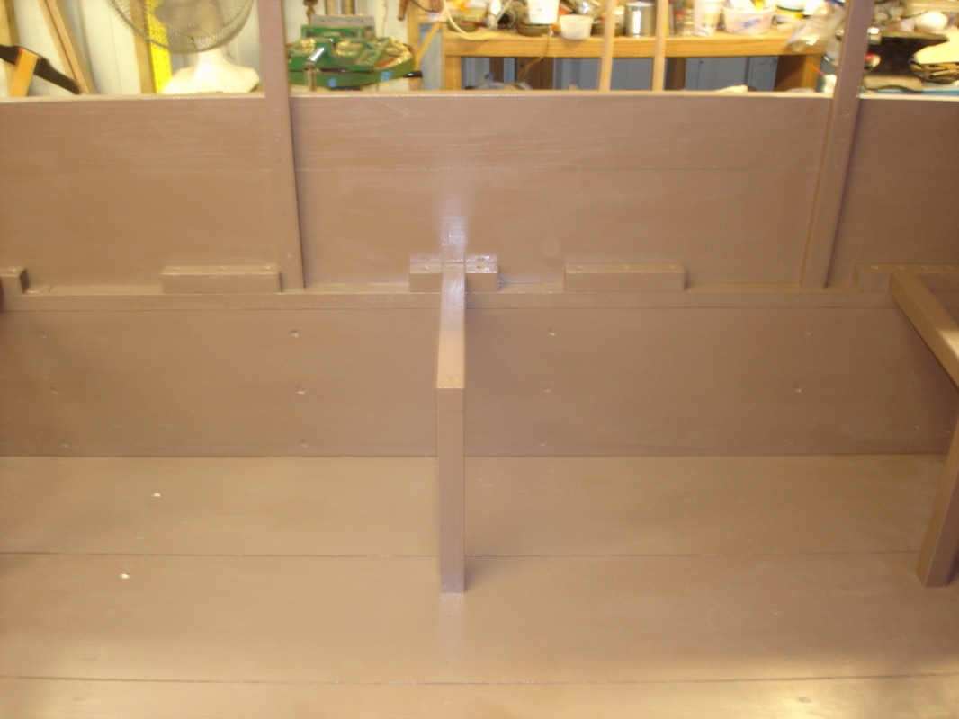
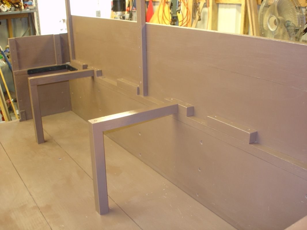
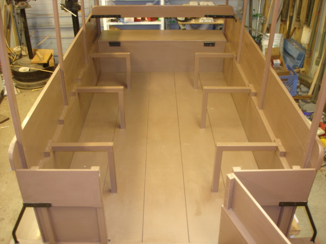
Final assembly: upright studs and cross pieces
I am now working on the inside of the ambulance body. The litters or benches are supported by the six upright studs and the cross pieces. The four wooden blocks on the top of the middle rail are hinge blocks which will support four strap hinges. There are a total of twelve strap hinges which connect the four litters and allow them to fold in and out to form one big bed or two benches. The litters are still under construction but I have temporarily set two of them in place so you can get some idea as to the purpose of the studs and cross pieces.
Contract specifications for the upright studs and cross pieces:
6 UPRIGHT STUDS 10 inches high, 1-1/4 inches square, with CROSS PIECES made of ash.
Photos of the upright studs and cross pieces:
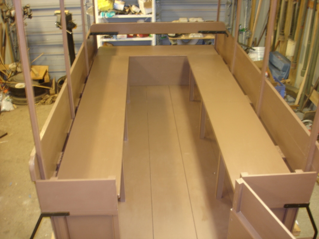
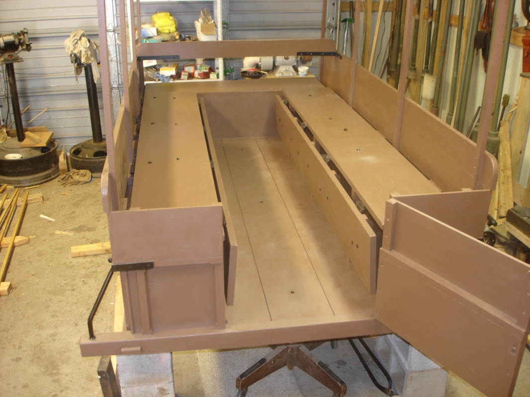
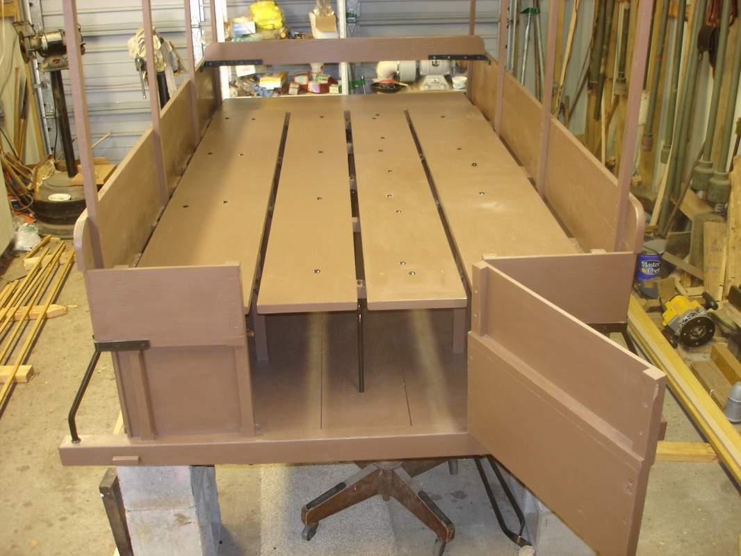
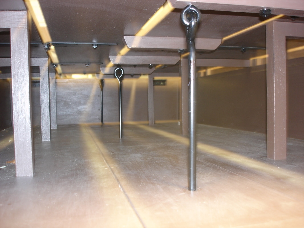
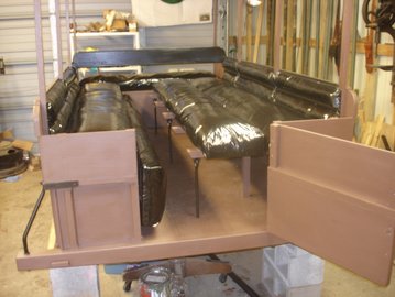
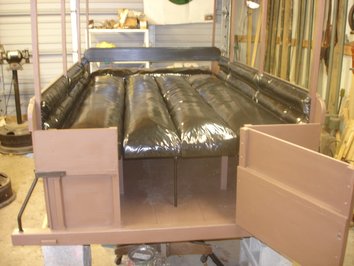
Twentieth posting – March, 2017
The litter
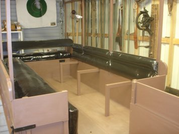
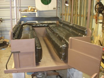
I have now completed the inside of the ambulance by installing the litter. The litter is made up of four separate parts or four boards which can be used as two benches, one bench and a bed, or two beds connected to each other. The litter is made up of eighteen moving parts plus three leather straps. The straps hold the folding legs out of the way when not in use. The construction of the ambulance is now completed. The next phase of the project is to upholster the driver’s seat, lazy back, litter, and back supports for the two benches.
Contract specifications for the litter:
1 LITTER divided into 4 parts 6 feet 3 inches long, 2 boards of litter next to panel, 12 inches wide by 3/4, the middle litter boards 9 inches wide by 3/4, poplar boards, with 12 strap hinges.
3 IRON UPRIGHTS with eyes fastened to cleats on middle boards, to be fastened with leather straps to boards.
Photos of the litter:

Twenty-first posting – April, 2017
Upholstery work
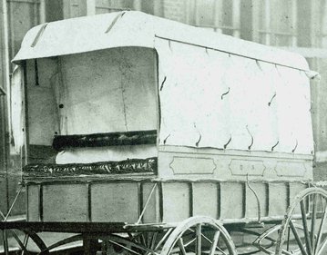
I have now completed all of the upholstery work on the ambulance. The upholstery work required me to hammer in just over 1,000 trim tacks and cut nails. I am showing you with photos a comparison of the prototype Wheeling ambulance submitted to the Quartermaster Department in March of 1862 and my Wheeling. Notice the high gloss finish on the oil cloth material. The material is known as black enameled oil cloth. It is very good at repelling fluids like water and all body fluids including blood.
Contract specifications for the upholstery:
The sides of body to be trimmed with the best quality of duck oil cloth, stuffed with curled horse hair; the mattress of litters of the same oil cloth and curled horse hair; one oil cloth covered cushion for front seat, stuffed with curled hair.
Lazy back covered with oil cloth and stuffed with curled hair, fastened to side rails.
Photos of the upholstery work:
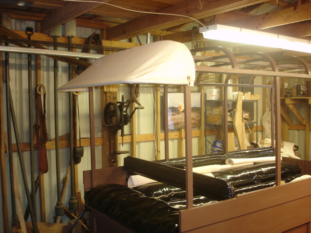
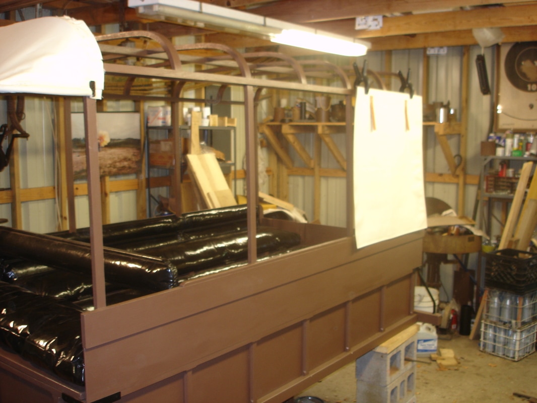
Twenty-second posting – May, 2017
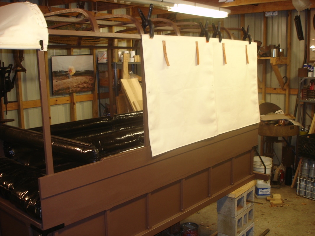
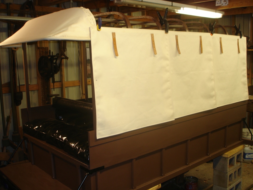
Canvas work
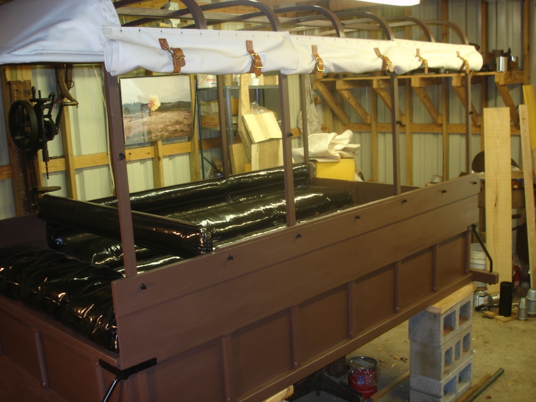
The canvas work for the ambulance is now underway. What you see in the photographs are three side curtains for one side of the ambulance body and the front bonnet. On the top of the side curtains are roll-up straps sewn into the canvas. The leather straps and buckles attached to the top of the side curtains allow you to roll the curtains up for more light and fresh air for the comfort of the occupants.
Contract specifications for the canvas:
12-ounce cotton duck, 28-1/2 inches wide, army standard, 3 curtains on side of body with leather straps sewed on with harness thread
Roll-up strap and buckles
Bonnet on front bow 12 inches
Photos of the canvas work:
Twenty-third posting – June, 2017
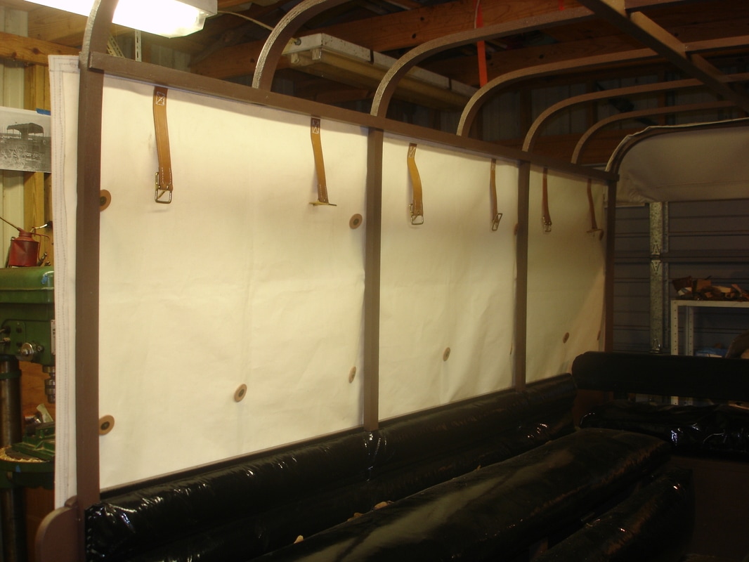
Pin straps and curtain studs
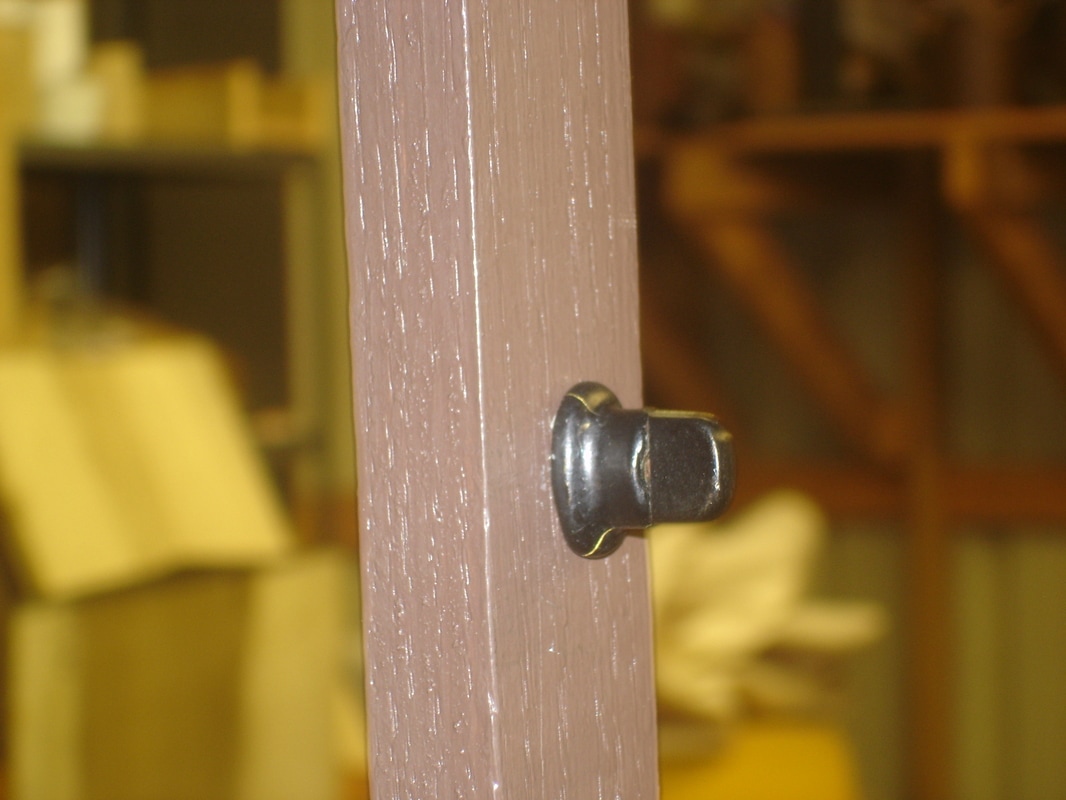
The pin straps and curtain studs have been added to one side of the ambulance body. The purpose of the pin straps which are riveted to the canvas is to hold the stretchers that were assigned to each ambulance. The curtain studs pass through the buttonholes in the canvas and also the grommets in the pin straps. After everything is connected the curtain stud rotates 90 degrees to lock it all in place. The canvas curtains are attached with upholstery trim tacks to the upper rail.
Contract specifications for the pin straps:
The pin straps to be riveted on the curtain.
Photos of the pin straps and curtain studs:
Twenty-fourth posting – July, 2017
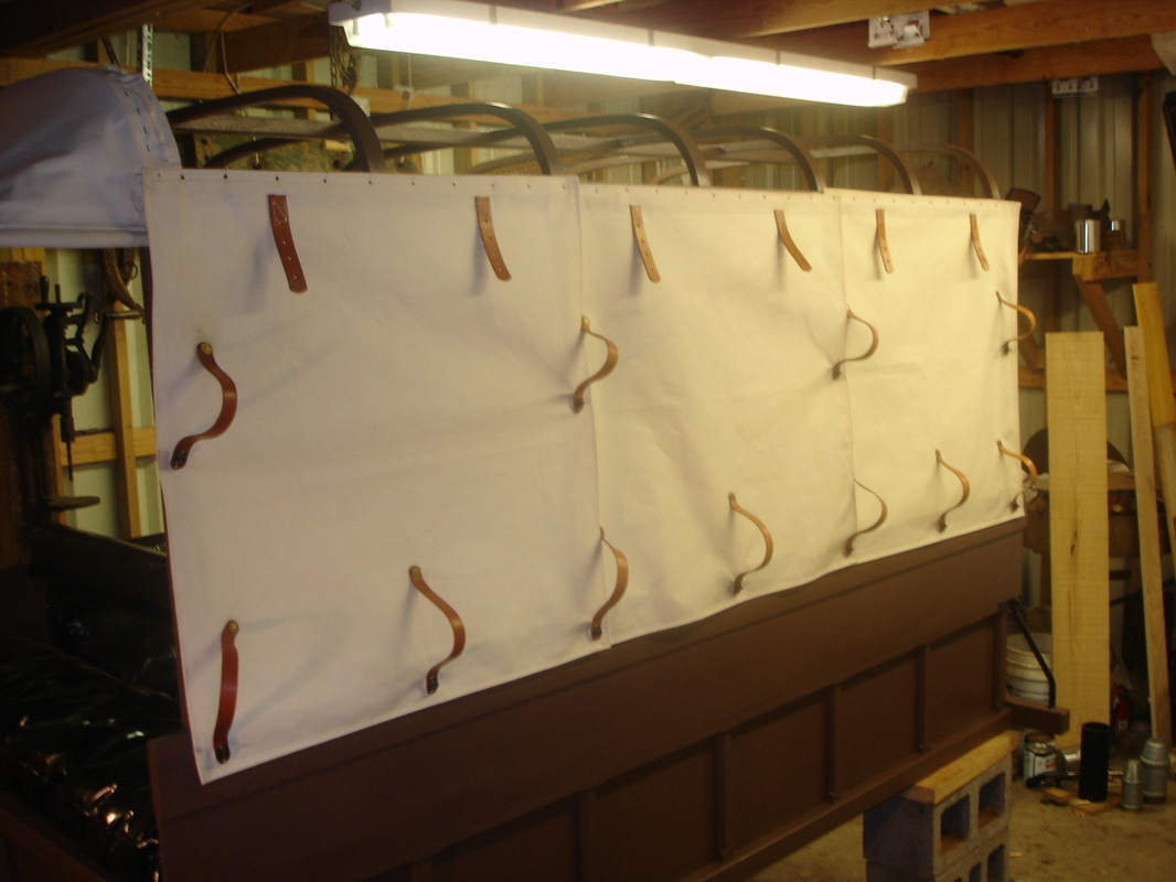
Completed canvas work
I am pleased to announce that all the canvas work has been completed. The end result is 32 hand stitched buttonholes, 48 leather straps, over 300 tacks and nails, 22 curtain studs, 33 brass and leather washers, 22 brass rivets, 2 wooden moulding strips and a whole lot of fun. Notice the wooden moulding nailed on along the top of the curtains. The moulding holds the roof canvas in place plus tying together the side and back curtains to the roof.
Contract specifications to complete the canvas:
Wooden moulding nailed over the heads of tacks on top of curtains
Photos of the completed canvas work:
Twenty-fifth posting – August, 2017
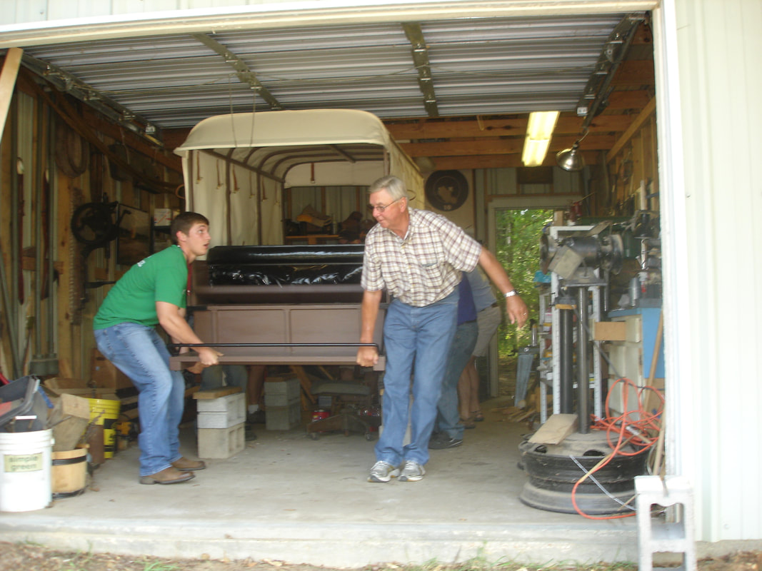
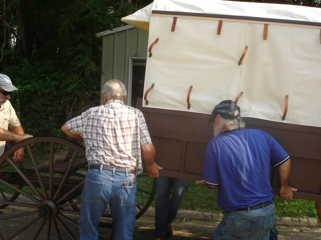
The marriage
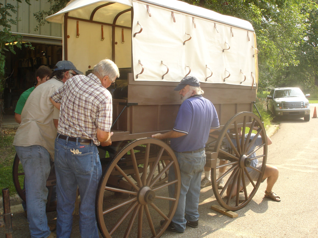
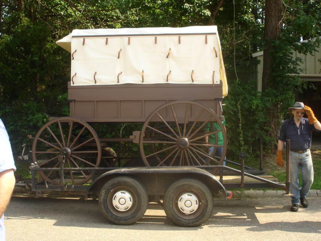
It took just over two years for it to happen but the union of the ambulance body and the running gear has at last come to be. I still have to install the brake activator and a few other small detailed items but the end of the project is very near.
I would like to thank all of those who participated as part of the “Amish Forklift” operation which lifted the ambulance body out of the shop and onto the running gear.
Photos of the marriage:
Twenty-sixth posting – September, 2017
Contract follow-ups
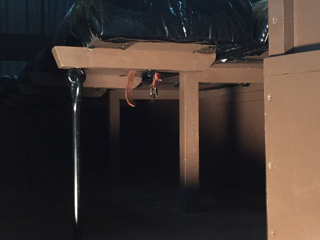
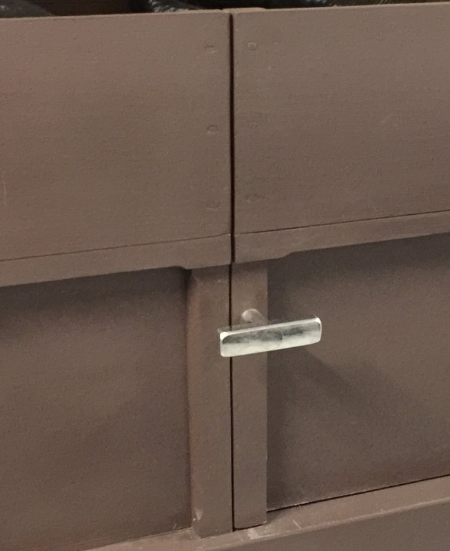
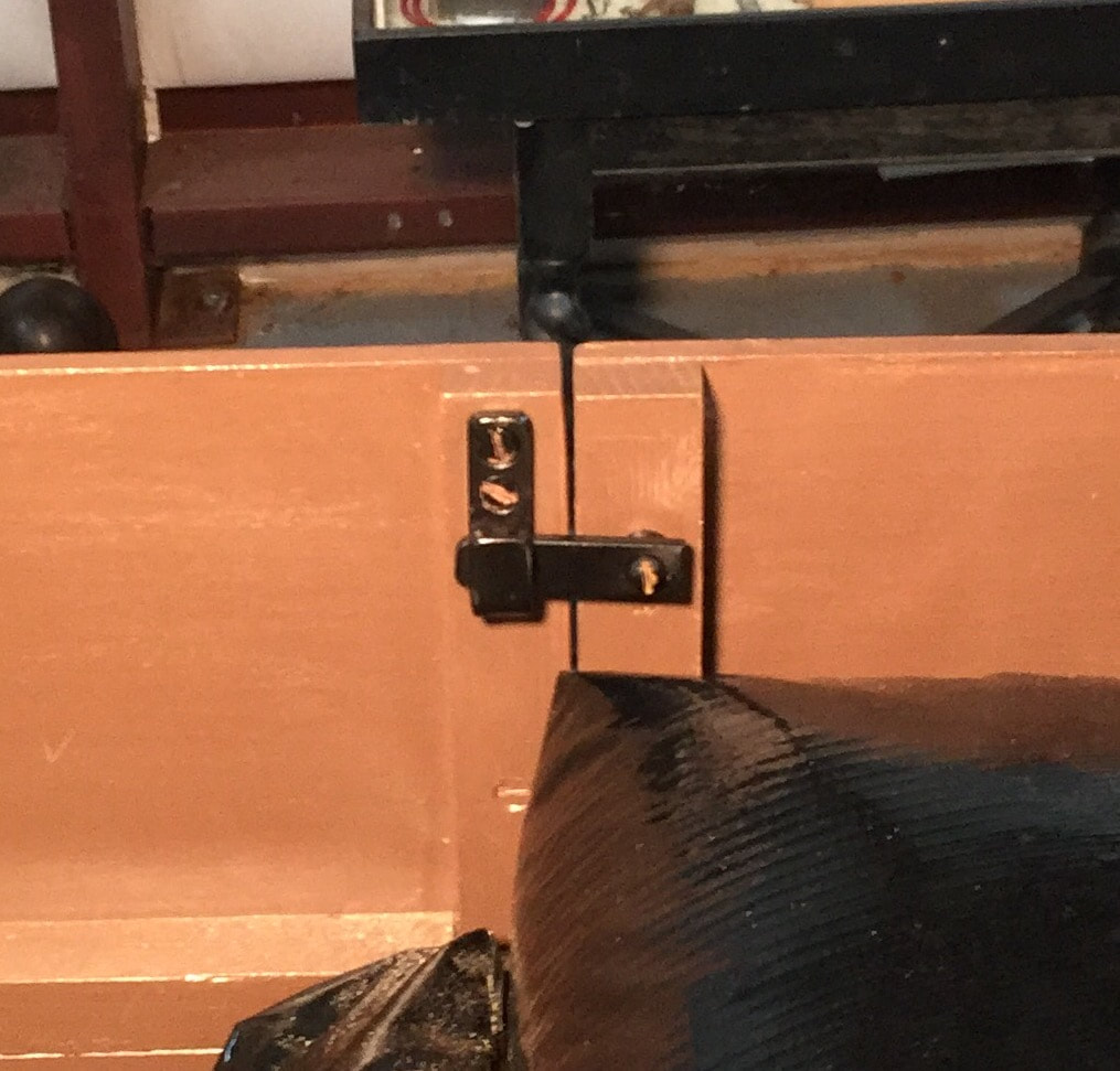
This month’s posting is going to follow up on a couple of items I said in previous postings that I would take care of at a later date. Also, I have a couple of small detailed items related to the ambulance contract that I would like to share with you. The first follow-up is from the March, 2017 posting where I mentioned the three leather straps which hold up the iron uprights to the middle litter when not in use. Now you can see one of the leather straps. The second follow-up is from the December, 2016 posting where I talked about the handle for the back door. I now have the silver plated door handle installed and the door lock as they were both called for by the contract specifications.
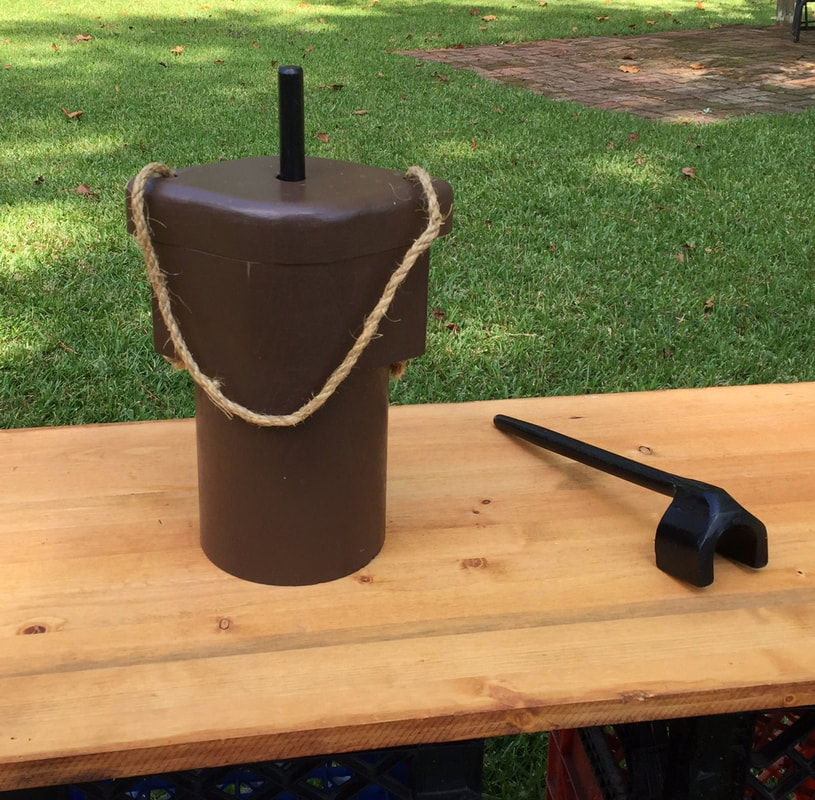
The contract also called for each ambulance to be supplied with a tar bucket which holds the grease used to grease the wheels and an axle wrench used to tighten the axle nuts which hold the wheels in place.
Photos of the leather strap, door handle, door lock, tar bucket and axle wrench:
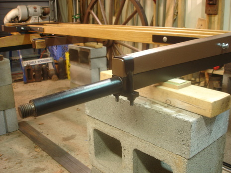
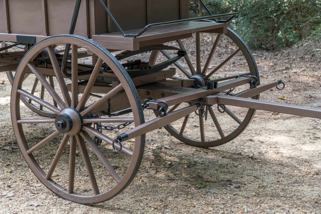
Twenty-seventh and final posting – October, 2017
The end of a journey (final posting)
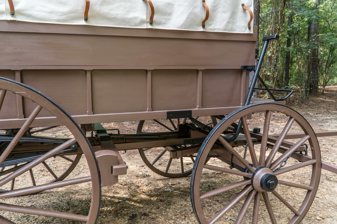
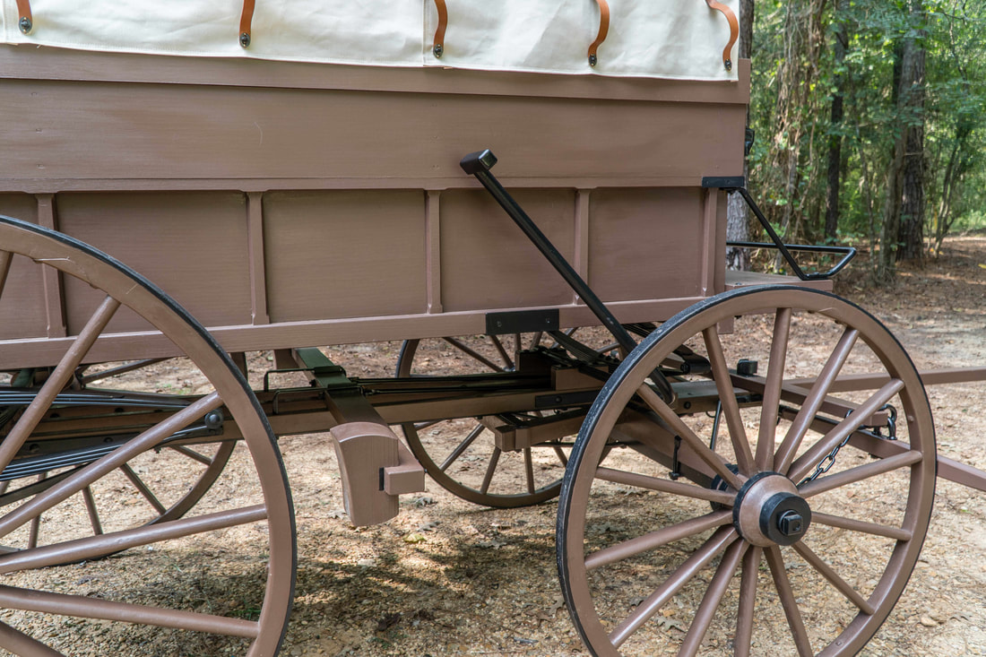
My journey to build a Wheeling ambulance has finally come to an end with the completion of the hand brake and the doubletree. The build has been a wonderful experience of exploration for information and inspiration. I have been blessed with the help of many different craftsmen and researchers who have lent me their special skills and insight. I have always said from the start of the project that it will take a whole village to help me build a Civil War Wheeling ambulance and I would like to thank all who have contributed.
The hand brake is a very simple design. Push the brake handle forward and the rub blocks push on the back wheels. Pull the handle to the rear and the rub blocks will release from the wheels.
The doubletree is the device which allows you to connect the harness horses to the vehicle. A team of two horses pulls the ambulance when it is in service. The Wheeling ambulance is now on display at the Starkville Civil War Arsenal in Starkville, MS. I hope you can plan a visit to the arsenal and come view the Wheeling.
Contract specifications for the doubletree and the singletree:
DOUBLETREE 4 feet long, 3-1/4 inches wide, 1-1/2 inches deep at center, tapered down at end 2-1/8 by 1-1/4.
SINGLETREE 2 feet 10 inches long, ironed same as omnibus.
For more views of the ambulance go to bit.ly/cwambulance.
Photos of the hand brake and doubletree:
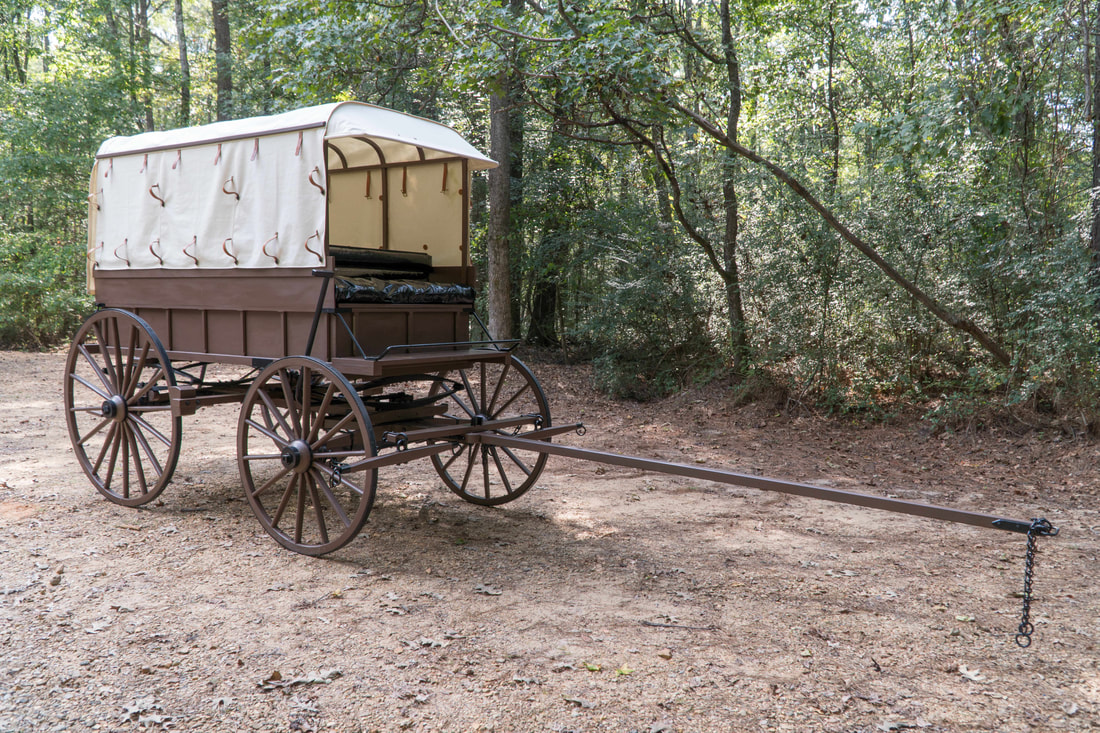
THE FINISHED PRODUCT
